Haven't tested with 117BL back then. So I can't tell. 170 - 117 have some other parameters different like output impedance, tempco.
PS for Pi?
Not sure if this is appropriate for this thread or if I should start a new one. My question concerns using the low voltage positive supply section of the black board for a linear power supply for a Raspberry Pi/DAC combo. The Pi recommends a 2A PS and the DAC sits on top of it and gets its supply from the Pi, so I am thinking maybe 3A max @ 5V. BJT or IFR? Any other issues to consider? I already have board (I used other two parts for +/- 25V.)
Thanks
BIB as is is not reliable for >1A. You would need slower big MOSFETS like IRFP9230/230 on big sinks to run 3A. But from what I see here https://learn.adafruit.com/embedded-linux-board-comparison/power-usage the Pi demands are lower. Measure your DAC demands also. A 0.1R in series with its now PSU feed could indicate by voltage drop across it and Ohm's law.
I have the Pi2 which is a quad core @ higher clock rate and more RAM than A/B and I have read reports that it "stumbles" on less than 1800mA (without the DAC) so I guess I'll have to look elsewhere.BIB as is is not reliable for >1A. You would need slower big MOSFETS like IRFP9230/230 on big sinks to run 3A. But from what I see here https://learn.adafruit.com/embedded-linux-board-comparison/power-usage the Pi demands are lower. Measure your DAC demands also. A 0.1R in series with its now PSU feed could indicate by voltage drop across it and Ohm's law.
Thansk
For Vref, I finally decided put a 1,6k resistor bypassed with a 150uF Rifa PEG124. I will listen to the result in a few days.
My CCS LEDs were all burned when I tried turning on the reg today and I had no idea why. I replaced them and everything is fine now.
My CCS LEDs were all burned when I tried turning on the reg today and I had no idea why. I replaced them and everything is fine now.
Maybe you use the 9610 on border constant current max and it gave turn on transient cut off leaving its CCS Leds exposed.
I think you are pushing the 9610 in "heroic" region. If you really need that hot-rod, then settle with a slower but stronger type. If not, 9610 is the better choice.
hello, i do the r6 mod but also add 10ohm resistor from g to source. the sound even more more smooth but lose bass power. this normal?
edit: sound very worse with 10ohm 😛
anywhere where resistor can benefit?
edit: sound very worse with 10ohm 😛
anywhere where resistor can benefit?
Last edited by a moderator:
As a very-latecomer to this thread, could someone point me to posts in which the noise performance may be discussed? Thanks in advance.
Clearly, if everything is working properly and in the absence of parasitic oscillations, the zener noise should dominate.
Brad
Clearly, if everything is working properly and in the absence of parasitic oscillations, the zener noise should dominate.
Brad
There was a Linear Audio Magazine survey with thorough tests by Jack Walton
The Salas regulator was an SSLV1.1 with couple of Leds & resistor Vref, just 100uF Vref filter capacitor, and 0.15A CCS setting
http://linearaudionet.solide-ict.nl/sites/linearaudio.net/files/V4 JW F5.pdf
http://linearaudionet.solide-ict.nl/sites/linearaudio.net/files/V4 JW F7.pdf
The Salas regulator was an SSLV1.1 with couple of Leds & resistor Vref, just 100uF Vref filter capacitor, and 0.15A CCS setting
http://linearaudionet.solide-ict.nl/sites/linearaudio.net/files/V4 JW F5.pdf
http://linearaudionet.solide-ict.nl/sites/linearaudio.net/files/V4 JW F7.pdf
Thanks! I even have that issue 🙂There was a Linear Audio Magazine survey with thorough tests by Jack Walton
The Salas regulator was an SSLV1.1 with couple of Leds & resistor Vref, just 100uF Vref filter capacitor, and 0.15A CCS setting
http://linearaudionet.solide-ict.nl/sites/linearaudio.net/files/V4 JW F5.pdf
http://linearaudionet.solide-ict.nl/sites/linearaudio.net/files/V4 JW F7.pdf
Brad
Last edited:
LEDs as references
One remark: Many LEDs have superbly low noise. They also have a significant temperature coefficient of the forward voltage Vf, which for some is a decent match to the Vbe of a silicon bipolar. This has been exploited by many in current generators, with a resistor in the emitter and the base tied to the LED, with the resulting collector current fairly constant with collector voltage and temperature. However the noise in the current is limited by the current noise in the emitter resistor, along with the shot noise in the base current and the thermal voltage noise of the base spreading resistance. The delta V, Vf -Vbe, is a bit low for best noise performance.
The quietest voltage reference I've found to date is when it is derived from a cascoded or multiple-cascoded JFET arrangement as a ~zero-tempco current generator. The reference voltage can then be developed across a parallel R-C and buffered. The low-frequency excess noise in particular can be exceedingly low, much better than any commercial voltage reference.
The somewhat-impractical aspect of such a reference is due to the wide parameter variations in JFETs, which require one to test a sample and make adjustments for low tempco.
The ref in the sslv is mainly Norton (the resistor) the led position(s) is for Vbe TC counteraction of the associated bipolar. A jfet ccs provides the collector current and no emitter resistor is used.
The ref in the sslv is mainly Norton (the resistor) the led position(s) is for Vbe TC counteraction of the associated bipolar. A jfet ccs provides the collector current and no emitter resistor is used.
Is the specific schematic somewhere in this thread?
Thanks,
Brad
They all are repeatedly, but since its long to dig now go to the bib builds thread. Has pdf on first post. http://www.diyaudio.com/forums/power-supplies/192625-sslv1-1-builds-fairy-tales.html
They all are repeatedly, but since its long to dig now go to the bib builds thread. Has pdf on first post. http://www.diyaudio.com/forums/power-supplies/192625-sslv1-1-builds-fairy-tales.html
Thanks, yes that is quite adequate.
Hi folks,
I've laid out a 70x36mm SSLV 1.1 PCB for 5V@20-40mA duty (~200mA CCS). Would appreciate another pair of eyes on it. I had to settle for 4.7uF MKS2 + 100nF MKP1837 for the Zobel due to size limits. The references are bypassed with 1uF MKP416.
Thanks.
I've laid out a 70x36mm SSLV 1.1 PCB for 5V@20-40mA duty (~200mA CCS). Would appreciate another pair of eyes on it. I had to settle for 4.7uF MKS2 + 100nF MKP1837 for the Zobel due to size limits. The references are bypassed with 1uF MKP416.
Thanks.
Attachments
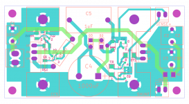
The loop areas aren't tight and long distance bypassing isn't productive, but it should work electrically. As for correct routing I am not sure, can't be following it in detail with a fast look. Just check everything twice.
P.S. Where are the Leds for CCS? Using one Vbe transitor current control voltage?
P.S. Where are the Leds for CCS? Using one Vbe transitor current control voltage?
- Status
- Not open for further replies.
- Home
- Amplifiers
- Power Supplies
- The simplistic Salas low voltage shunt regulator