is that surface temperature of jfet, or nodes of actual circuit temperature? kelvin or celsius?
at 1 W, the jfet was barely warm at all...but 1.2W was getting on warmy-hot side
1.8W my thumb felt a bit on the uncomforble-pain side.
at 1 W, the jfet was barely warm at all...but 1.2W was getting on warmy-hot side
1.8W my thumb felt a bit on the uncomforble-pain side.
Last edited:

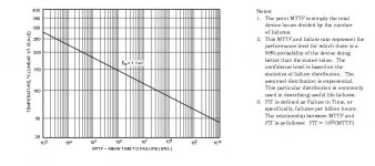
Looks like ~20Cdegrees to ~30Cdegrees cooler/hotter results in ~ 4times longer life.
In the middle of the plot, a reduction from 150°C to 100°C gives ~ 50times longer life. A further reduction from 100°C to 60°C gives ~100times longer life.
Running at 60°C, instead of 150°C gives ~4000times longer life !
This will vary a lot depending on plastic package, or metal package.
Salas,
I think your "double" is quite misleading.
Especially in view of the post that followed asking C or K
A more often seen estimation for longevity is:
double the life for a 10Cdegrees reduction on operating temperature.
Last edited:
An old military applications engineer told me that a long ago for finished products. If its too rough, then it is, but that is what he told me. "Each time the operating temperature doubles son, products come back for service four times sooner."
Alright, it is not misleading, your old pal's rule is wrong.
Double the temperature of 25°C is 323°C (~298K to ~596K)
Double the temperature of 25°C is 323°C (~298K to ~596K)
Depends on what he had in mind, if he meant a doubling due to natural ambient temperature, say field equipment moved form a moderate to a hot country military base, then 15-20C to 30-35C is ~two times ten dif, roughly four times less life expectancy.
"The life of an electronic device is directly related to its operating temperature. Each 10°C (18°F) temperature rise reduces component life by 50%*. Conversely, each 10°C (18°F) temperature reduction increases component life by 100%"
Temperature vs Reliability | FirePower Technology
"The life of an electronic device is directly related to its operating temperature. Each 10°C (18°F) temperature rise reduces component life by 50%*. Conversely, each 10°C (18°F) temperature reduction increases component life by 100%"
Temperature vs Reliability | FirePower Technology
But what is a sensibly reliable threshold? Maybe no more than 80C junction temperature in max ambient is logical.
"Typically a problem in avionics and military equipment, excessive heat can wreck havoc in an electrical system. Component parameter values usually vary with temperature and it is important not to exceed the manufacture’s temperature range. Above such temperatures, parts are no longer guaranteed to be within specification. Typically, this can range from 80C to 150C"
Topic: Electronic/Electrical Reliability

Calculator values
I want to build a PS for my MF V-Dac II 12V 500mA. I have the board and the IRF minikit.
I read the manual and I am in the middle of this enormous thread and reading other threads about the SSLV.
Since I am a bit of a noob and learning doesn’t comes naturally I am afraid that I will do something wrong and kill my SSLV.
I want to build a PS for my V-DacII 12V/500mA
I have 50VA 18v toroid
I am struggling with some values in the calculator.
DC in is this 18 x 1.141= 20.5?
Constant current (Q101) = 500 + 20% ( I see this value is that influences R301)
Q303 = standard value is now 4 and I don’t have measured value myself
R303 = 1.8kOhm this was in the manual..
The results I now have are
R301 = 5.2Ohm/1.88W
R305 = 250 Ohm
I like to know if this correct so I can order some things and start my build….
DC in proves practically less than textbook due to losses. Maybe ACx1.3-1.35 at those levels
500mA + 30% maybe you can afford
Q303 better measure IDSS and enter 18% less than that in the calc
Measure your LEDS VF with 9V battery and 2.2K resistor in series, enter those readings
Your R301 & R305 results should get more lifelike after the above steps.
Your dummy test load 25R 10W.
500mA + 30% maybe you can afford
Q303 better measure IDSS and enter 18% less than that in the calc
Measure your LEDS VF with 9V battery and 2.2K resistor in series, enter those readings
Your R301 & R305 results should get more lifelike after the above steps.
Your dummy test load 25R 10W.
Unexpected problem with IDSS
As mentioned by Salas I measured the LEDS with a 2.2K resistor and entered the reading in the calculator, NO problem there.
Then I went on to measure the IDSS on the jfets. Because I didn’t know how to do this I searched the internet.
When I use the schematic as shown in the picture my DMM won’t give a results…?
Then I searched the Internet a bit more and went for the method of measuring the drop voltage across a 10 OHM resistor connected to the drain and dividing this by the measured resistance. This gives readings which I think aren’t right.
An IDSS of 1,15mA for Qx03does not seem right or does it?
So I checked my (cheap) DMM and it seems to all right , because other measurements seem to be all right. To be sure I replaced the battery.
What I like to know is?
Is my DMM ill?
Am I doing something wrong?
Or is my second system of measuring the IDSS wrong?
……
Or am I losing my mind?
Well I hope that this sounds for familiar?
Attachments

Use 100 Ohm, maybe your DMM is not accurate on low mV. Make sure that G+S are shorted during the test. In the series mA DMM mode method you shown on the picture make sure you use the series current socket on the meter. There are also many fake 2SK117, 2SK170 on ebay etc. if yours aren't coming from a mini-kit. 1.15mA is not right, 2SK117GR spec is 2.6~6.5 mA.
Worst case scenario...
Well from all the causes to my "problem" mentioned it is the worst case scenario..
I was the one who did it wrong (i won't go into the very stupid details).
Now I have IDSS values between 3.6 and 5.5.
With the side notes Salas gave I now have:
R301 3.9 Ohm/1.63W
R305 324 Ohm
The R305 value looks a bit low to me because when I lower the R303 value (1,8K taken from the manual) the R305 shoots up rapidly..
But maybe this just a silly thought.
Did you remember to reduce the actual Q303 idss by 18% for entry?
Use 500R or 1K trimmer to have leeway.
Use 500R or 1K trimmer to have leeway.
- Status
- Not open for further replies.
- Home
- Amplifiers
- Power Supplies
- The simplistic Salas low voltage shunt regulator