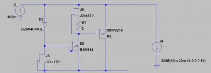
is something like this a good idea?
mosfet instead of bjt...
mosfet instead of bjt...
Attachments
Last edited:
D2, M1, noisier stuff.is something like this a good idea?
mosfet instead of bjt...
To put it a nice way...
Would someone please point me to the most current
SALAS PSU and Phono Stage BOM, Board GB, Kits, Etc...
Much appreciated..to bad this platform still runs on 20 year old software and it is impossible to find anything, unless you got 897455 hours to spend on reading threads with 10304808 posts....Very educational and all, but after spending 65 hours entertaining myself I would like to have some satisfaction and build some gear....Please have mercy!
Latest linear low noise PSU:
Latest CNC, schematics:
Latest Salas PSU:
Latest Salas Phono:
Bom, Schematics, PCB purchase options.
Thanks a million! (Am I even on the right forum?_
GB for Salas Folded Simplistic Phono PCB http://www.diyaudio.com/forums/group-buys/241736-gb-salas-folded-simplistic-phono-pcb.html
D2, M1, noisier stuff.
zener is for simplicity, i never thought about using it...
as for mosfet:
m1 much noisier?
thought bjts were noisier...
 ...how come?
i thought j6 on my schematic would sink a bit of noise...?
i thought j6 on my schematic would sink a bit of noise...?
not sure about that one lol...

That one's better. MOSFET is the noisy 1/f guy. Seen any phono stage with MOSFET input stage?
BTW have you measured BSP129 IDSS ?. I have 20pcs or so and while it starts at ~ 60mA very soon it drifts up fast while still warmish not hot. Talking 3 times up and going.
That one's better. MOSFET is the noisy 1/f guy. Seen any phono stage with MOSFET input stage?
phono is not my generation....i m more ipodish...
sometimes i guess ill play with that....most natural source i ever heard was definitly vinyl...
BTW have you measured BSP129 IDSS ?. I have 20pcs or so and while it starts at ~ 60mA very soon it drifts up fast while still warmish not hot. Talking 3 times up and going.
isnt it typical of mosfets to change current if Vgs remains the same...?
i always used a few ohms to degenerate and it was not a problem if i remember...
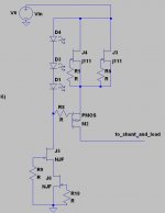
you want to try a b1 style buffer if i remember correctly?
how is that for a ccs for around 100ma?
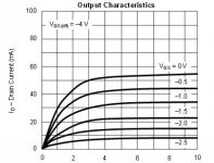
graph is j111...
graph is j111...
Attachments
Last edited:
Pushing J111s thermally maybe. (J3,4).
P.S. VfLeds-PMOSvgs must be > J11s Vgs (off) so to work as CCS well.
P.S. VfLeds-PMOSvgs must be > J11s Vgs (off) so to work as CCS well.
yes...one would have to watch for a nice Vds without overheating...
still i like the idea very much and will probably be my next regulator CCS build
wich rises the question again....where are those to-92 heatsinks hiding on this planet?
that is why i make my own minimalist ones...
still i like the idea very much and will probably be my next regulator CCS build
wich rises the question again....where are those to-92 heatsinks hiding on this planet?
that is why i make my own minimalist ones...
Digikey have them Invalid Request
yes i know these exist.
though i have not tried them, i m wondering how effcient they really are. the part that joins the ''helmet'' to the actual heasink looks like it has a smallish cross-section, which would limit their range of effectiveness. Maybe the to-92 are not made for high level of dissipation, but with the zetex e-line to-92 style mosfet, i succesfully put around 1.250 watts. with the face against a ''big'' heatsink(530002B02500 Aavid Thermalloy | Mouser) the device casing remained at almost room temperature. but when i put one device on each side facing with 2.5w total, the thickness of the aluminium,the portion between the two devices, proved to be to thin to acommodate such power, and as a result the device casing heated up considerably compared to room temperatue.
i thought the following might inrest some.
today, i tested the fairchild j111 package temperature for different wattage, using a simple but effective method.the goal is to see what kind of wattage is ''safe'' for my minimalist heatsink.
the face of the transistor (part that diffuses the most heat) was place against a 1mm or so thick aluminium piece and with my thumb against the backside of the jfet. paste was used in between.
with an idss of around 100mA, the jfet was tested with different Vds and it seems that 1 watt(10Vds) is about the limit where i can feel my thumb having a marked rise in sensation of heat. in other words, i could actually feel my thumb sinking heat.
so take the result as seriously as you want, but i personally would not put more than 1 W on this jfet with the minimalist heatsink i built (jfet squeezed between 2 aluminium bars, or plate, depending on how you shape it).
for more wattage, you would have to pot the whole thing, or use a helmet style fitting and even then i,m not sure if the nodes inside the casing would nt overheat anyway, regardless of the heatsink...
Last edited:
- Status
- Not open for further replies.
- Home
- Amplifiers
- Power Supplies
- The simplistic Salas low voltage shunt regulator