If you will use only active voltage reference component(s) the drift will be mainly governed by their spec. Any additional passive resistive element in the Ref (I see a trimmer in your photo) will translate the temperature settling of M2 VGS and the PPM of R6 by I to V action. Also the PNPs 2Vbe drift will add to Vo, but its minor percentage. The total drift it can be insignificant or objectionable regarding the application. Its not critical to start at 12.04V on powering an analog circuit and end up with 12V after a while for instance. These reg circuits are not conceived with precision applications in mind, but they can have a respectable amount of it if you will skip the adjustable Vo trimmer facility and rely on stiff active voltage references only. Wide bandwidth low flat Zo and low noise with minimal components in no series pass is their prime line of characteristics.
Thanks Salas for your quick answer, I just want to make sure I didn't implement it wrongly. Now I can relax and enjoy my new toy 🙂.
Use only LEDs in the Vref if it not must be adjustable. Simple, cheap, low noise, effective. How many for your Vo target, 5-6? Try now that is handy on the breadboard out of curiosity. No, you do nothing wrong. These are hot running circuits, will show some temperature settling.
Buy a few dozen IR LEDs. These generally have a lower Vf.
You can mix and match the red and IR LEDs to give the Vref you require without having to include an adjustable resistor.
You can use a variable current CCS for the Vref string. This allows you to trim the Vref voltage by a few percent, since Vref is dependant on the current flowing through the LEDs/Zener/resistor string.
Once you know what Vref components get you into the output voltage ball park you adjust the CCS current to trim the Vref and finally swap the variable CCS current resistor element to a fixed resistor.
This does not get rid of drift due to semiconductor parameter drifting with temperature. But it does allow removal of resistance in getting your final voltage and this reduces the overall drift percentage.
...You can use a variable current CCS for the Vref string...
Thanks Andrew for your suggestions. To use a "variable current CCS", would a JFET with G and S connected by a trimmer serve the purpose?
if you are using a high gm device like the sk170 or bf862 then you need a quite low value resistor in the Source lead. Try a 100ohm VR.
Reflektor for Preamp Power Supply
Hi Salas
I would like to replace my PS Audio Preamp "Power Supply" with Reflektor,
hope may improve sound quality.
PS Audio Preamp use transistor MPS8099 and MPS8599 with data as below :
Vceo = 80 Vdc
Vcbo = 80 Vdc
IC = 500 mAdc
PD = 625 mW
Original Power Supply :
2 EA Troid Transformer CT, 24 - 0 - 24 VAC / 1 Ampere (Dual Mono)
Target Output voltage : 26 - 28 VDC.
I do not know power consumption, because I have no tool to measure it,
as well as no operating manual.
This old Flat Preamp, only volume control without trebel and bass control,
build maybe 1979 by Paul McGowan president of PS Audio - PS Audio
I only have DMM, it is possible to me to build Reflektor, please advise.
If possible, please info the lastest schematic of Reflektor suitable to my
preamplifier.
I confuse to use the correct Zobel value.
1. 2R2 + 2.2 uF
2. 2R2 + 0.22 uF
3. 0R47 + 0.22 uF
5. 0R2 + 2.2 uF
4. 1R + 470 nF
6. 1R + 33 nF
Regarding heatsink for M1 and M2 can I use heatsink data as below :
Length : 41.6 mm (1.638 inch)
Width : 25 mm (0.98 inch)
Height : 38.1 mm (1.5 inch)
Thermal Resistance (C/W) = 3.8
Surface Area = 13.765 mm2
Thank you for your help.
Rgds,
Sun
The voltage is high limit the current is high limit in those MPS transistors, we don't know the real dynamic consumption of the pre though. If we must meet max of those transistors, then spare for M2 is high also since it will need burn double. If not, maybe your sinks could do. Better make some series reg you may fancy or a capacitance multiplier... Else, we need full data of that load. A current limited shunt plan must know all for any answers.
Thanks Salas for your replay.
Could you info me easy way, how to calculate full data of that load.
Do you think Series Reg or Capacitance Multiplier better than original LM317 and LM337.
I do not have any reference how to build Series Reg or Capacitance Multiplier, please advise.
Rgds,
Sun
Could you info me easy way, how to calculate full data of that load.
Do you think Series Reg or Capacitance Multiplier better than original LM317 and LM337.
I do not have any reference how to build Series Reg or Capacitance Multiplier, please advise.
Rgds,
Sun
You can break the series connection from PSU to peamp, restore the break with 1 Ohm resistor and calculate current by Ohm's law. Volt over resistor/1 Ohm.
Look for Keantoken work, has special multiplier one you can use easier, small not hot, very good. Can pass 400mA linear per side. http://www.diyaudio.com/forums/power-supplies/177516-keantokens-cfp-cap-multiplier-71.html
Look for Keantoken work, has special multiplier one you can use easier, small not hot, very good. Can pass 400mA linear per side. http://www.diyaudio.com/forums/power-supplies/177516-keantokens-cfp-cap-multiplier-71.html
Salas, thank you for your info.
You mean calculate current same as procedure to adjust current bias in Power Amplier class A/B.
Keantoken multiplier looks suitable to me, again thank you for your suggestion.
Rgds,
Sun
You mean calculate current same as procedure to adjust current bias in Power Amplier class A/B.
Keantoken multiplier looks suitable to me, again thank you for your suggestion.
Rgds,
Sun
i had a smoke from one of my regulator, and now the pot doesn't alter the voltage, which stays fixed at (input voltage-2v). both the mosfets still get hot to the touch, and all the resistors read fine, all the leds come on. which component should i troubleshoot first?
Q105 Q104 (205,204). What happened? Some intervention or on its own? Talking about that small sinks one on own layout in the DAC?
i misused it, definitely. was powering 2 tda1387 up to 15v, the mosfets got so hot yet i neglected to put a bigger heatsink.
My Second Reflektor
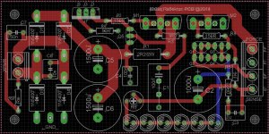
A local DIY friend has happily taken over my first Reflektors (well, for free), after he was impressed by the SQ improvement it brought vs his LM317 supplies, and I made a second PCB which can take more LEDs, TO-247 MOSFETs, and use off-board heatsinks 🙂
A local DIY friend has happily taken over my first Reflektors (well, for free), after he was impressed by the SQ improvement it brought vs his LM317 supplies, and I made a second PCB which can take more LEDs, TO-247 MOSFETs, and use off-board heatsinks 🙂
Attachments
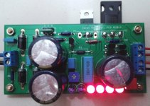
You are mixing IR LEDs too I guess. Are you happy with the LEDs only (almost) Vref drift now?
Yes, the one in the picture has 4 LEDs and 2 IR-LEDs, giving 10.1V and it drifts far less than before 🙂
Next thing I'll try is to put it on a massive heatsink, change R1 to 0.47R/5W and see if it can give 1.3A.
Next thing I'll try is to put it on a massive heatsink, change R1 to 0.47R/5W and see if it can give 1.3A.
Don't do that with IRF9610 before you will inspect its datasheet carefully and make sure its internal temperature will stay at safe level on that sink along with the output MOSFET. The 9610 is a 20W at 25C max device, its in twilight zone when >1A and every operation parameter you decide or any heat transfer deficiency counts. There are stronger P-MOSFETs but more capacitive. If you will be obliged to choose stronger one, watch the Ciss parameter to be best available in power class.
Thanks Salas, I forgot to mention that M1 is currently FQP7P06 (45W/7A max, ciss 225p) and M2 is IRFP140N, would they be OK?
I want to compare if it will bring improvement over the AMB Sigma11 that is currently supplying my Raspberry Pi, and it takes up to 1A, though I probably won't use it for the long term due to the heat.
I want to compare if it will bring improvement over the AMB Sigma11 that is currently supplying my Raspberry Pi, and it takes up to 1A, though I probably won't use it for the long term due to the heat.
- Status
- Not open for further replies.
- Home
- Amplifiers
- Power Supplies
- The simplistic Salas low voltage shunt regulator