
how long the sensing wires should run, as close to the load ( as a 4 wire connection) or is it ok terminate them in board itself and just two wires going to load?
Even 5cm or 10cm of wiring is worthwhile to be executed in 4 wire Kelvin mode. If the real consumption nodes of the load circuit are further away than their PCB marked receiving points, its very worthwhile to over run long PCB tracks and solder the 4 wires to those real nodes directly.
Even 5cm or 10cm of wiring is worthwhile to be executed in 4 wire Kelvin mode. If the real consumption nodes of the load circuit are further away than their PCB marked receiving points, its very worthwhile to over run long PCB tracks and solder the 4 wires to those real nodes directly.
What are the advantages/issues of doing the perfect kelvin mode vs just two wire to the load? What character of circuit is affected?
Depends on the dynamic nature of the load. In general the error correction amplifier in the reg works on a more true to life signal. Subjectively people describe the effect as more firm and transparent.
Thanks Salas. Do you think I can connect the ground of this circuit to my amp and DAC ground?
Hi Salas,
It's hard to find Sk170 in my town, so may I change it to K30A (reverse pinout). I saw datasheet and they are nearly same specs.
With BJT and FET, can you suggest specs for them so I can replace with same one with same specs. I have alot of pulled-out FETs from industrial controller pcb.
Thanks so much !
Hi Salas,
It's hard to find Sk170 in my town, so may I change it to K30A (reverse pinout). I saw datasheet and they are nearly same specs.
With BJT and FET, can you suggest specs for them so I can replace with same one with same specs. I have alot of pulled-out FETs from industrial controller pcb.
Thanks so much !
For which version; There are some 1.0 and 1.2(R) with few K170 until SSLV1.1 and the Reflektor. Those use the 2SK117GR. No K170 in PCB releases other than DCB1s. K30A has differences. Shows less Yfs, more VGS(OFF), its better noise spec range is for higher impedance.
If I use K30A (cheap and easy to buy) and same specs FET/BJT instead of those in your recommended BOM, the board will not as good as your design but will it be better than LM317+TL431 ? (I'm using it now).
I'm going to upgrade power for buffer, pre-amp and dual Wolfson WM8740 DAC.
Thanks for your reply !
I'm going to upgrade power for buffer, pre-amp and dual Wolfson WM8740 DAC.
Thanks for your reply !
Still you don't refer to the specific version. In 1.1 no they won't work OK especially in the Vref. To be better it has to be correct first. Make a two Leds Ref Reflektor for 5V in the DAC at least that has BJTs mainly (you can use 2N4403 very common, or BC560 little more noisy) and BF245A or 2SK30ATM for J1.
did anyone used with a good final result in their Salas Reflektor these transistors BCV62B and/or MMBT4403?
http://www.farnell.com/datasheets/775182.pdf
https://www.fairchildsemi.com/ds/2N/2N4403.pdf
what do you think about them ?
http://www.farnell.com/datasheets/775182.pdf
https://www.fairchildsemi.com/ds/2N/2N4403.pdf
what do you think about them ?
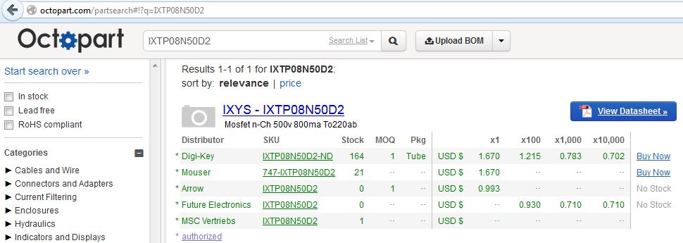
I am wondering about the availability of Depletion MFETs like the DN2540. Which ones are available around the world? I like this one:
Invalid Request
Invalid Request
It works for me. Here is the datasheet:
http://ixdev.ixys.com/DataSheet/DS100178A(IXTY-TA-TP08N50D2).pdf
http://ixdev.ixys.com/DataSheet/DS100178A(IXTY-TA-TP08N50D2).pdf
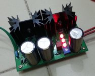
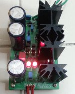
My Reflektor is up
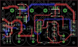
I use the Reflektor as an exercise to learn using PCB software, and draw my first ever PCB.
I should have made the main PCB trace wider, and several other things could be done better - but I'm just glad that it is working the first time round. One issue was that as I use IRLZ24N for M2, where it's Vgs is on the low side, I have to replace the trimmer with a 2K one in order to reach the 10V needed.
Attachments
Last edited:
Reflektor is friendly enough to get going.
What voltages across R1 & R5 for how many mA average load consumption?
What voltages across R1 & R5 for how many mA average load consumption?
Voltage across R1 is 0.64V, R1 is currently 3R3 so current is less than 200mA, when all testing are done I'll change R1 to 2R2 to give around 290mA. Given the small onboard heatsinks (rated at 3.7C/W), I'll not go above 300mA.
Voltage across R5 is 2.12V when R5 equals 1K. I realize that by changing R5 to 250R, voltage across R5 lowers slightly to 2.08V but Vout can exceed 10V even with a 500R trimmer. So I'm wondering what should be the "right level" of current at the current mirror.
Voltage across R5 is 2.12V when R5 equals 1K. I realize that by changing R5 to 250R, voltage across R5 lowers slightly to 2.08V but Vout can exceed 10V even with a 500R trimmer. So I'm wondering what should be the "right level" of current at the current mirror.
Don't play with R5 downwards because it lessens the gain of the error loop. What you saw is by doing that you also boost the current in one side of the mirror which gives more to the Vref on the other side too. Its not bad you got a bigger trimmer if Vo is stable. Although you could have used more LEDs instead. Is Vo 10V stable in your build?
- Status
- Not open for further replies.
- Home
- Amplifiers
- Power Supplies
- The simplistic Salas low voltage shunt regulator