In the execution. Matter of carefully debugging. Without good photos at least nobody else than you can even guess.
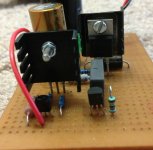

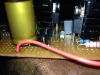
Photo the wiring also. Now, those sinks are nothing for 700mA. Use R1=10R for 60mA. Use a dummy load resistor for 10-30mA consumption and wire it on output correctly by the force and sense wires. At safe low power now you can debug it, and only then try high mA on large side sinks with the MOSFET tabs insulated. If you had it run with those sinks at 700mA at all and you felt high heat on the MOSFETs they are probably dead by now. Also, the voltage part will not work without the sense wires meeting the force wires on some load.
P.S. Say if you wanna simulate 20mA consumption at 10V you need 500R dummy. Rdum=Vout/IoutTarget.
does it need seperate wiring for sensing and load?.Those sinks never got even warm. I havenot connected any loads across.Is it needed to get a voltage out?
Attachments
Last edited:
does it need seperate wiring for sensing and load?.Those sinks never got even warm. I havenot connected any loads across.Is it needed to get a voltage out?
You surely need to close circuit for the sense part. You did not get it running current is fortunate with such R1 and small sinks. Make R1 10 Ohm. Your back wiring picture shows clean work. See how to wire the dummy in this example.
Attachments
Huray...got it working with dummy load.As you mentioned the heatsinks are getting hot. I just turned it off. So even if the device not drawing current of 700mA I still have to use a higher value resistor for such heatsink?Reading 4.981V
If you got 20Vin and 5Vout for example, the heat dissipated can be calculated for the 9610 as ICCS*(20V-5V). For the output MOSFET as (ICCS-ILOAD)* Vout. In all cases.
With the sinks you now got you would not want more than 2W on each MOSFET+Sink, tops.
ICCS=VR1/R1=VBE/R1 as we said. So make your predictions. R1=5R6-10R with a dummy calculated for 20mA could be safe as it is made now, just for testing.
With the sinks you now got you would not want more than 2W on each MOSFET+Sink, tops.
ICCS=VR1/R1=VBE/R1 as we said. So make your predictions. R1=5R6-10R with a dummy calculated for 20mA could be safe as it is made now, just for testing.
Invalid Request
This is the one I got, I guess the max current is way below 300mA?
http://www.digikey.com/product-sear...e=us&keywords=HS115-ND&formaction=on&x=7&y=17
This is the one I got, I guess the max current is way below 300mA?
http://www.digikey.com/product-sear...e=us&keywords=HS115-ND&formaction=on&x=7&y=17
It says 24C/W. Don't let more 2W on each as I wrote. Don't guess, use the formulas I gave you, plug in your settings.
How to calculate the R1 ? I am confused.Is it not that VBE is available only when you have R1 in the circuit?I am getting a reading of 0.6Volt for VBE,For a current draw of at least 600mA ,I calculated the resistance as 1 Ohm. Will a heatsink of 6Watt at 37degree Celsius will be good enough?
VBE is available both in circuit across R1 or when testing the relevant transistor alone with various methods or when reading its datasheet VBE curve at its intended bias current (~2mA). Anyway, your 0.6V VBE reading is trusty, 1 Ohm R1 for 600mA is correct. For your 20Vin and 5Vout at 0.6A you are looking at 9W dissipation on the 9610 & 1.5W on the MTP3055VL for 300mA average load draw. You could use 15Vin for 6W on the 9610. Or 12Vin for 4.2W. Your now transformer may duck a few Volt below its now otuput when run heavy also. I would expect ~50C on a common to both MOSFETS 2.5C/W sink with 15Vin and 20C room ambient. If keeping with 20Vin then 1.5C/W is needed for about the same result. When with 12Vin 3.5C/W would suffice. That 6W at 37C sink you ask about is an -above ambient- spec? Then its a 6C/W sink, i.e. not enough. R1 should be 1-2W power rated with bit raised leads above board level to breath.
Power Dissipation @ Temperature Rise 10W @ 50°C
Thermal Resistance @ Natural 3.8°C/W
Power Dissipation @ Temperature Rise 6W @ 37°C
Thermal Resistance @ Forced Air Flow 3.5°C/W @ 200 LFM
Thermal Resistance @ Natural 3.8°C/W
Power Dissipation @ Temperature Rise 6W @ 37°C
Thermal Resistance @ Forced Air Flow 3.5°C/W @ 200 LFM
The first one is good for the output MOSFET only at 1.5W-2W dissipation.
The second one is good for the CCS MOSFET only if you will arrange the raw input voltage down to 12-13V DC. Use a lower secondary transformer, or burn about 7V on a CRC using a 12 Ohm 12W resistor. Something.
The second one is good for the CCS MOSFET only if you will arrange the raw input voltage down to 12-13V DC. Use a lower secondary transformer, or burn about 7V on a CRC using a 12 Ohm 12W resistor. Something.
calling digikey to change my order to get the second heatsink. I think all otheroptions of heatsink are rather cumbersome for such a small board
- Status
- Not open for further replies.
- Home
- Amplifiers
- Power Supplies
- The simplistic Salas low voltage shunt regulator