That's it! Removing the acrylic at the load solved the problem...
Can you explain what happened here? I would like to understand also what the possibilities and limitations are on local decoupling...
This is very interesting to me. What are/were the distances involved, through the traces and ground plane, between each of the reg's output points, the top and bottom of the zobel, and the cap's two leads (and the load's pins)? Can you possibly show a diagram of that part of the layout?
This is very interesting to me. What are/were the distances involved, through the traces and ground plane, between each of the reg's output points, the top and bottom of the zobel, and the cap's two leads (and the load's pins)? Can you possibly show a diagram of that part of the layout?
Sure... interesting to me as well....
Attached the layout, let me know your thoughts.
Note that the crossed out cap positions are unused, and the 100R at the output is not used either. Actually Salas suggest to put a 1R at the output, so that position is 1R now.

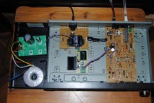
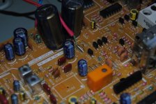
My p2p BiB is working steady as a rock... Thank you Salas for the perfectly clear instructions in the pdf and Merlin for the fets.
I am using a Block TX with double secondaries (2 x 15Vac) to produce 14Vout from the BiB.
I am only using one winding and would like to parallel the second winding to lower output imp of the TX.
The TX has four wires coming out in the following order: Black, Red, Yellow, White
Black and Red form one 15Vac winding, Yellow and White form the other.... how should I connect them to get 15Vac out with double current capacity ?
I will do black parallel yellow and red parallel white before connect I will measure with DMM that measures 15VAC
Sure... interesting to me as well....
Attached the layout, let me know your thoughts.
Note that the crossed out cap positions are unused, and the 100R at the output is not used either. Actually Salas suggest to put a 1R at the output, so that position is 1R now.
View attachment 291860
That 1R was to see where we were getting at. No need to keep it if you test its all quiet even without it now.
Sure... interesting to me as well....
Attached the layout, let me know your thoughts.
Note that the crossed out cap positions are unused, and the 100R at the output is not used either. Actually Salas suggest to put a 1R at the output, so that position is 1R now.
View attachment 291860
Sorry if this is mostly just speculation, at this point.
Is it maybe a stability problem involving the remote-sensing feedback loop?
Where were your probe and probe ground, exactly? And what is the fundamental frequency of that oscillation?
What happens if you try a larger (or smaller) value decoupling cap?
Please forgive me for not reading most of this thread, but what is the input voltage and what is the maximum possible current draw, for your circuit?
200 kHz might be high-enough for most audio power amplifiers but the supply rail trace length (inductance) might be too much for that, without decoupling capacitance. If it were tens of watts, I would think that you would need at least 220 uF decoupling, with maybe 3-4 cm max total length for cap connections to device power pin and ground, including cap lead spacing. Is this a low-power application? Or can you try moving the device much closer to the regulator output, so maybe no decoupling would be needed?
Regards,
Tom Gootee
hi,
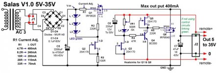
I've built another v1.0 salas reg for +5v. It's working fine, though a bit weird is that I set the voltage to 5.00vdc and after about 10-15min it raises to 5.15vdc...in an hour time to 5.20v...doesn't go higher. Is that normal with v1.0?
I've got about 14vdc after rectification
233mA transformer
elna caps (C7 - 47uf & C6 - 2x100uf)
FC in PS (2x 2200uf)
Q1 & Q6 - IRF9520
The reg is used as analogue supply for two Wolfsons WM8740. According to the manual it should be feeded with 13mA per chip, so 26mA in total + 30mA for the reg itself, that was the goal.
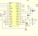
Another question is that do I need to keep 47uf caps near WM8740's pins (AVDD1) as it was designed originally in the DAC (att.) or just stay with 47uf Tonerex that I used in the reg's output? Previously Wolfsons were feeded with one LM7808 -> two smd LM 5v regs. All three regs have been swapped to a single salas v1.0.
would very appreciate any advice!
I've built another v1.0 salas reg for +5v. It's working fine, though a bit weird is that I set the voltage to 5.00vdc and after about 10-15min it raises to 5.15vdc...in an hour time to 5.20v...doesn't go higher. Is that normal with v1.0?
I've got about 14vdc after rectification
233mA transformer
elna caps (C7 - 47uf & C6 - 2x100uf)
FC in PS (2x 2200uf)
Q1 & Q6 - IRF9520
The reg is used as analogue supply for two Wolfsons WM8740. According to the manual it should be feeded with 13mA per chip, so 26mA in total + 30mA for the reg itself, that was the goal.
Another question is that do I need to keep 47uf caps near WM8740's pins (AVDD1) as it was designed originally in the DAC (att.) or just stay with 47uf Tonerex that I used in the reg's output? Previously Wolfsons were feeded with one LM7808 -> two smd LM 5v regs. All three regs have been swapped to a single salas v1.0.
would very appreciate any advice!
Attachments
To avoid drift measures resistance in the trimmer & change for a low ppm fixed resistor. Do you have a scope? if yes see if with the 47uF near the DAC you have ripple or oscillates, if I remember well all shunt regs designed by Salas don't like a cap between the reg & the load.
Last edited:
Just measure my salas v1 regulator using irfp240, feeding 3 pcs of lm4562ha for iv converter and differential amp for my 1794 dac. Input is about 22VDC and output stable at 11,89V both for positive and negative rail. But something strange happened, output current for positive rail was 65mA and 89mA for negative. Is this normal? as the opamp should just require 10mA per IC.
Regards
🙂
Regards
🙂
After regulator. My R1 current is 95 mA for positive and 150mA for negative as I use 20R for positive and 13R for negative.
Regards
Regards
I measure output current by measuring voltage accross 1R resisitor in series with load.
Regards
Regards
This is My DAC
1 : - 11.87V
2 : + 11.87V
3 : + 5.02V
4 : + 5.02V
Try to measure any ripple or oscillation, using Uni-T DMM Scope. No AC coupling in the scope so I add 100nF coupling capacitor in the posistive lead.
Any Oscillation there?
Current measurement by using DMM mA meter. 11.87V on output. Supply 3 pcs of LM4562HA for IV converter and differrential amp for PCM1794
Is it normal? AFAIK the opamp should need only 10mA per IC. And is it normal that the - Rail consumption almost 2 times than + rail?
Regards 🙂
An externally hosted image should be here but it was not working when we last tested it.
1 : - 11.87V
2 : + 11.87V
3 : + 5.02V
4 : + 5.02V
Try to measure any ripple or oscillation, using Uni-T DMM Scope. No AC coupling in the scope so I add 100nF coupling capacitor in the posistive lead.
An externally hosted image should be here but it was not working when we last tested it.
Any Oscillation there?
Current measurement by using DMM mA meter. 11.87V on output. Supply 3 pcs of LM4562HA for IV converter and differrential amp for PCM1794
An externally hosted image should be here but it was not working when we last tested it.
Is it normal? AFAIK the opamp should need only 10mA per IC. And is it normal that the - Rail consumption almost 2 times than + rail?
Regards 🙂
That has to do with your circuit, the power source (i.e. the reg) can't determine the load's current draw, only limit it if its not set above its max demand, which is not the case here.
P.S. No oscillation, but you scan very slowly also. Looks like its just your 50Hz hum (fits 20mS=50Hz). Can it be done at 50uS to make sure? Did you have 1R too when doing that scan?
P.S. No oscillation, but you scan very slowly also. Looks like its just your 50Hz hum (fits 20mS=50Hz). Can it be done at 50uS to make sure? Did you have 1R too when doing that scan?
Dear Salas,
No 1R when doing scan. Regulator connected directly to load.
This is 10uS scan for regulator output. DAC's SPDIF input fed with 1kHz Sinus datastream, analog output is about 162 mVAC p-p 1 kHz sinusoidal waveform.
What do you think about the result?
Regards 🙂
No 1R when doing scan. Regulator connected directly to load.
This is 10uS scan for regulator output. DAC's SPDIF input fed with 1kHz Sinus datastream, analog output is about 162 mVAC p-p 1 kHz sinusoidal waveform.
An externally hosted image should be here but it was not working when we last tested it.
What do you think about the result?
Regards 🙂
Dear Salas,
No 1R when doing scan. Regulator connected directly to load.
This is 10uS scan for regulator output. DAC's SPDIF input fed with 1kHz Sinus datastream, analog output is about 162 mVAC p-p 1 kHz sinusoidal waveform.
What do you think about the result?
Regards 🙂
Very good.
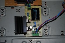
P2P BiB powering AN6554 output quad opamp in technics Tuner.... Wow 🙂
Many analogue an output usually appreciates it.
Dear Salas,Very good.
Thank you very much for your information. So, it's like no problem on regulator. Still confusing whether there are faulty in my opamp or this is the normal operation. Anyone with same experience?
Regards 🙂
- Status
- Not open for further replies.
- Home
- Amplifiers
- Power Supplies
- The simplistic Salas low voltage shunt regulator