Using dummy load 16R 25W I read 1.88V & the current R1 0.116A so I will reduce R1 until get 0.30A to see if I read the suggested voltage in the dummy load.
Last edited:
Rod told you to reach 0.29-0.3A. Tune your R1 further less.
P.S. Ooops, Rod's about, we crossposted. He will let you know more.
P.S. Ooops, Rod's about, we crossposted. He will let you know more.
OK, should get ~ 5V across R1.
If you have 5V, use R1=15R - should give 0,3A
Changed R1 to 15R, now I have 1.85V across R1 (0.123A), 9.14V across Leds.
Rod I have other Tx 8.5V could be better?
Now parallel the 15r & 16r.Changed R1 to 15R, now I have 1.85V across R1 (0.123A), 9.14V across Leds.
Rod I have other Tx 8.5V could be better?
You should get just less than 0.116A + 0.123A ~ 0.23A
Now find the resistor required for the remaining ~70mA, somewhere between 27r and 39r.
BTW all of these resistors can be 500mW or 600mW size.
If you had 20r or 22r, then three of 600mW would be almost perfect.
Have you read WJ yet?
Have a look at Walt Jung's papers describing simple and more complicated current regulators. The simplest uses just 2 components, a resistor and an LM317.
Last edited:
17.67Vdc allows ~11V of drop across the current regulator for ~6V across the heater filament. That's OK.
How low will the 17.67Vdc go when the mains is at lowest voltage and the heater/s is/are drawing correct current?
How low will the 17.67Vdc go when the mains is at lowest voltage and the heater/s is/are drawing correct current?
This is OK.
Now, R1 must have ~5V across it?
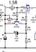
What is Ok, Quang Hao schematic?
no.
The original LED string creates a big reference voltage.
The Vbe in Quanghao pic develops a small reference voltage.
The original LED string creates a big reference voltage.
The Vbe in Quanghao pic develops a small reference voltage.
Please ignore the Quanghao drawing, unless you want to change to a much lower power supply, and use this totally different circuit!
If you have a 17-18V supply, 9,2V across the LEDs, you should be OK. Just check for 5V across R1, then change the value of R1 until you get 0,29 to 0,30A
If you have a 17-18V supply, 9,2V across the LEDs, you should be OK. Just check for 5V across R1, then change the value of R1 until you get 0,29 to 0,30A
What is Ok, Quang Hao schematic?
Quanhao schematic is NOT OK. There is likely to be stability problems, if you build the circuit like that.
I notice that Quanghao is attempting to sell filament regulators on his site, using design elements copied from my DIY kit filament regulators (he bought one last month to get a closer look). I should make it clear that, although he is using my description "Gyrator + CCS" filament regulator, this circuit is not designed by me, nor am I able to support it. AND, If the snapshot above is used in the regulator, there is VERY likely to be trouble from oscillation, and other effects as well.
The parts of the design taken from my kits were used without the politeness of asking if it was OK.
OK, should get ~ 5V across R1.
If you have 5V, use R1=15R - should give 0,3A
It's not clear, when you said 5V across R1 is the dummy load right?
Quanhao schematic is NOT OK. There is likely to be stability problems, if you build the circuit like that.
I notice that Quanghao is attempting to sell filament regulators on his site, using design elements copied from my DIY kit filament regulators (he bought one last month to get a closer look). I should make it clear that, although he is using my description "Gyrator + CCS" filament regulator, this circuit is not designed by me, nor am I able to support it. AND, If the snapshot above is used in the regulator, there is VERY likely to be trouble from oscillation, and other effects as well.
The parts of the design taken from my kits were used without the politeness of asking if it was OK.
I am sorry to read that.😡
- Status
- Not open for further replies.
- Home
- Amplifiers
- Power Supplies
- The simplistic Salas low voltage shunt regulator