well just for good measure I just reflowed everything (not much of a task, pretty small component count) plus actually soldering the wires shorting the sense connections (I had just bent a couple thickish resistor leads into them) and everything now seems fine, I had it set for just over 12vout across the 150R, and this time it measured a steady 94ma, with no undue heat, but given your comments on how hungry it is I set this down to 11vout, but now the current reads 76ma. is this normal?
I dont really feel confident starting a thread for this GB, as the way I understand the etiquette, there is some degree of responsibility to answer questions being the thread starter and I dont know that I know enough about the circuit at this stage. if you feel that is not my responsibility then i'll start it because I agree this thread has moved onto more current designs and should not be cluttered with posts like mine ad-nauseam. I paused before posting my query in here I didnt know where else to post as the GB isnt the right place either.
anyway as long as its normal to need to reset the current with each Vout adjustment (which does make sense) then another V1 reg lives. thanks for your help guys
Last edited:
11/150=73.33mA. Since its not a lab resistor, and 11V on display can be having a tolerance, so it goes for showing 76mA also, I think its showing pretty much Ohm's law. Fine result. The current has to do with what your application draws plus some to keep in the reg for its own use and low Zo. It does not tie with setting Vo changes. Its constant. You can suggest in the GB if they want you or if someone else wants to open a builders thread as a showcase or for exchanging experiences, telling them that you are not opening it as a guy for answering, but as a home. There are many boards out there by now and they will soon be using them for all kinds of applications so it would be nice they know where to look for finding each other I would think.
ok the current changes as the amount of current formed over the resistive load for a different voltage changed; seems like everything is in order. though the amount of change seems too much, with ohms law the vout would need to be over 14v (about 14.2) to give 94ma across 150R and i'm certain it was never that high; but I suppose the Vout may have been borderline too high given the Vin and causing oscillations? anyway at the lower Vout everything seems solid and the numbers make sense, I wont waste any more of your time
OK i'll ask in the thread. i'm with you, its win win IMO too, keeps this thread clear for questions regarding the current state of development and gives those in the GB somewhere that questions specific to this version and this PCB -posed by people in the same boat are at.
cheers
OK i'll ask in the thread. i'm with you, its win win IMO too, keeps this thread clear for questions regarding the current state of development and gives those in the GB somewhere that questions specific to this version and this PCB -posed by people in the same boat are at.
cheers
Last edited:
shunt for filament SRPP 6922
I'm trying to set the filament current for SRPP 6922 to 0.3A & 6.1V, I'm using GH Salas Low Voltage Shunt Regulator, looking for dummy load I calculated by ohms law:
R = V / I
R = 6.1V / 0.3A = 20.33 ohms
About power needed for dummy load:
W = V x I
W = 6.1V x 0.3A = 1.83 watts
So I used a 20 ohms 5 watts resistor for dummy load, I used a 12v 5A Tx because shunt needs a Vin-Vout 6-10V difference, I used R1 (adjust current 4R33 & get 1,368 across R1 to have 315mA, that's the theory but when connect to the filament tube the maximum voltage I can reach is 2.19-2.24V with the 5K trimmer....Led 4 lit only a bit....& tubes don't lit...
Thanks for help
Last edited:
huh? posts I read in here and the GB thread ....
Hi Qusp
Would you please point me the GB thread ?
Regards
Ricardo
Hi Qusp
Would you please point me the GB thread ?
Regards
Ricardo
http://www.diyaudio.com/forums/group-buys/174421-salas-low-shunt-group-design-salas-54.html
Hi,
the heater supply specification is generally an AC voltage and an approximate current consumption (demand) at that voltage as a guide for sizing the secondary winding.
You can use DC and supply a fixed DC voltage and again the current is a guide to heater current consumption.
Alternatively, one can choose to supply the filament with current using that guide figure. This can be either AC current or DC current.
DC current is easier to set and hold than AC current.
It looks like you have opted for the current method. This does not need a voltage regulator. It needs a current regulator.
The Salas style Shunt regulator is a voltage regulator using an integrated Current regulator to achieve voltage regulation.
If you want the DC current method do not use a Shunt regulator.
You need to select a CCS (current regulator). It would be completely wasteful to discard the Shunt part and use only the CCS part of the Salas Style Shunt.
Select a CCS dedicated to supplying 300mA continuous DC current.
Have a look at Walt Jung's papers describing simple and more complicated current regulators. The simplest uses just 2 components, a resistor and an LM317.
Last edited:
Hi,
the heater supply specification is generally an AC voltage and an approximate current consumption (demand) at that voltage as a guide for sizing the secondary winding.
You can use DC and supply a fixed DC voltage and again the current is a guide to heater current consumption.
Alternatively, one can choose to supply the filament with current using that guide figure. This can be either AC current or DC current.
DC current is easier to set and hold than AC current.
It looks like you have opted for the current method. This does not need a voltage regulator. It needs a current regulator.
The Salas style Shunt regulator is a voltage regulator using an integrated Current regulator to achieve voltage regulation.
If you want the DC current method do not use a Shunt regulator.
You need to select a CCS (current regulator). It would be completely wasteful to discard the Shunt part and use only the CCS part of the Salas Style Shunt.
Select a CCS dedicated to supplying 300mA continuous DC current.
Have a look at Walt Jung's papers describing simple and more complicated current regulators. The simplest uses just 2 components, a resistor and an LM317.
Thanks for the input, learned other electronics lesson, sorry for my ignorance.
Now go to valves/tubes and ask them for recommendations on heater supply for your particular application.
It's OK, valves/tubes will come here to you!
Andrew is correct, you don't need a shunt regulator for indirect heated tubes like 6922.
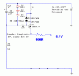
If you have already made a SSHV, just use the IRF9620 current source, Q1.
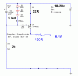
Use Green LEDs x 5, and make R1=22R, to give 0,29A.
Power on, check voltage across heater. Add 100R resistors until you get 6,1 to 6,25V; for 6922
Thanks Rod, like this schematic with R1 22R for 0.29A & five Leds instead 3 Leds, (Tx 12V 5A?):
This will be OK. The supply voltage should be 18 to 20V for this circuit.
For a dummy load to test 6922 heater, use 2x 33R 5W wirewound - in parallel [shunt]. Connect the dummy load, and measure the voltage. this dummy load will give about 4.7 to 4.9V when the current is 0.29 to 0.30A. When you see this voltage, you can safely connect to the 6922 heater, and check for 6.1 to 6.2V.
BTW, If you use a bipolar PNP [eg TIP42], and 2x green LED, you can run from 10 to 12V - but that is a different circuit!
Its very near to what Rod told you to use. Why not? Only expect a bit less voltage developed over it than the targets he gave you, since its 0.5R less than 33R/2.
- Status
- Not open for further replies.
- Home
- Amplifiers
- Power Supplies
- The simplistic Salas low voltage shunt regulator

