Is the BC550CG a direct replacement to BC550C ?
Comparing specs on Mouser yields no obvious differences.
See attached pic (left BC550C, right BC550CG).
They are identical. The CG suffix must either mean Pb free or its they post them only to down town hotels.😀
post3375
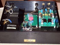
is there a connection missing: R10 to LED D1?
Andrew,
Good eyes! I built it with the connection between R10 and D1. But will go back and make sure that the schematic has that dot - as the schematic is linked to the PCB.
Thanks,
Ken
Salas,
Well, I'm back... turns out I spoke to soon. With the fixed value resistors in place (setting Vout), the voltage is still rising. Slower than before, but, still rising. I've also reduced the current to about 70mA with by using 10 ohm at R1 instead of 3.3 ohm. My chip need about 15mA. All the diodes are in place an shining brightly, no oscillation on the scope. The voltage setting resistors are 1watt 10k for negative and 11k for positive.
Thoughts?
Ken
It does not stop rising after there is top temperature reached on everything? How much it backed off with one LED, maybe two could harness it a bit better? Also if you try connect an electrolytic cap across the reference resistor, say 100uF, what happens?
It does not stop rising after there is top temperature reached on everything? How much it backed off with one LED, maybe two could harness it a bit better? Also if you try connect an electrolytic cap across the reference resistor, say 100uF, what happens?
Salas,
It doesn't stop rising... ran it for 30 plus minutes and it just keeps going up, slow, but steady. I'll give both of these ideas a try. To be clear, LED should be in series, yes?
Thanks
Ken
what currents and voltages are changing to cause the drift in output voltage?
check the currents and voltages on both sides of the sensing/measuring bridge.
I just checked a 3LED string with a bf244a in Quanghao PCB.
from 20V down to 12V the current fell linearly @~0.2mA / volt.
below 12V down to 5V the current fell faster and faster the lower the voltage.
However when measuring the voltage across the LED string. It held steady to 3 sig fig from 20V down to 9V and then fell very slightly down to about 6V. The LED string could not hold a constant ref voltage when supply fell below 6V. This shows that Quanghao circuit for 5V and above does not allow bf244a to be used as the CCS at the low voltage end. sk170 would perform better at the 5V to 8V range. A cascoded jFET would perform even better.
You need to understand what is happening to work out a solution.
Volts and amps will tell the whole story.
Thanks. I’ll try the same solution on V1.00 / C1 and let you know.
Last Saturday were changed the no name C1 orange 4.7uf/100V MKT capacitors with Wima MKS4 4.7uf/63V, but I take worse results. So yesterday evening I changed again to orange and the sound came back. With Wima it had narrow stage, unclear bass and treble and abnormally voices. In my case, at this position, the orange caps are far better.
MKS and MKT are very similar, some even say they can be the same.
I wonder if one of the capacitors is faulty?
I wonder if one of the capacitors is faulty?
MKS and MKT are very similar, some even say they can be the same.
I wonder if one of the capacitors is faulty?
Who knows? The truth is that the sound changes dramatically
I am not a chemist, but Wima's page shows polyester, polyethylene, terephthalate, PET and MKS, all for the same capacitor dielectric.
It appears to me they know as little of the chemistry as me.
It appears to me they know as little of the chemistry as me.
I experimented with those MKS and also found they produce nasty results.
Polypropylene is acceptable but better is polystyrene and even better Silver Mica.
Polypropylene is acceptable but better is polystyrene and even better Silver Mica.
Well... it all depends on the overall cook.
Some components work better in some places, always depending on the rest of the layout.
In my case, I find vref caps to determine tone effectively but these depend on the caps used as smoothers in the psu and also the caps used in the riaa RC filtering circuits. It took me a whyle to figure the best combination for me.
- Status
- Not open for further replies.
- Home
- Amplifiers
- Power Supplies
- The simplistic Salas low voltage shunt regulator