Hi ikoflexer!
What do you think when I change Zenner diot 4.7V by one adjust????
An what the value of adjust?????
Good or not good???when use adjust change zenner diot???
Because supply + and - out is not the sample!
Thank!
I'm not sure I understand... but if you want the voltage output to be the same, 5V, on both the positive and the negative regulator, then you can use LEDs in series instead of the zener. You can try different LEDs and see which ones will give you the output that you need.
Hope this helps.
Also, in your schematic, the negative regulator has the zener incorrectly drawn, it should be reversed.
I'm not sure I understand... but if you want the voltage output to be the same, 5V, on both the positive and the negative regulator, then you can use LEDs in series instead of the zener. You can try different LEDs and see which ones will give you the output that you need.
Hope this helps.
Ok! thank
What number Leds i can use! I want out put + - 5 V for my DAC!
And the value of Leds ??? yellow LEDs or Green LEDs?
Thank you very much!
Quang Hao
Also, in your schematic, the negative regulator has the zener incorrectly drawn, it should be reversed.
Ok! i change it!
but the vout is not the sample!
Why??
+ V -out = 4.9 v
- V- Out = 4.75 v
Now Im doing and ask you!
Pm: You have Messenger
My nick : ********
I want chat with you? ok or no??
Attachments
Also, in your schematic, the negative regulator has the zener incorrectly drawn, it should be reversed.
ok!
you can see again!
thank!
Attachments

1k trimmers instead of zener or 2.2Vf matched leds X2 are your alternatives. Their polarity same as those 3 for the CCS in each respective +/- reg.
Ok! i change it!
but the vout is not the sample!
Why??
+ V -out = 4.9 v
- V- Out = 4.75 v
Now Im doing and ask you!
Pm: You have Messenger
My nick : ********
I want chat with you? ok or no??
No personal data on open forums. We can not be responsible of any abuse.
 There is the pm service for personal exchange.
For hifinutnut
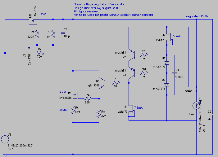
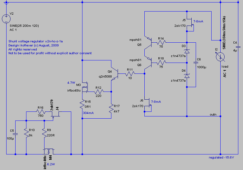
Positive and negative versions of v2, for 15V out, about 350mA load, another 350mA goes through the shunt mosfet. All using n-channel mosfets, one can use different mosfets than what I show here, with little change to the schematic.
Comments on the positive one will apply to the negative version as well. J3 and R7 set a mini-CCS so the voltage drop across R2 biases M2. Do not take the value of R7 and R2 as given in the schematic more than a rough approximation. You'll have to find the value that gives you the correct bias so that you have the desired total current limit. I like to choose R7 for a current of about 500uA going through the mini-CCS. This depends on the Idss/pinch-off voltage of J3. I hook up J3+R7 to a 9V battery and choose an R7 that gives me 500uA.
R6 is not necessary, I use it to measure the current through the shunt mosfet M1. I think of this current as "reserve" current, which is used to do the needed regulation as more or less current is drawn by the load.
Assume that the Idss of jfets in this schematic is between 7 and 8 mA.
It's very important that Q2 and Q3 are RF transistors.
Take the value of C2 only as an indication. The ideal value is no cap at all, but start low and go up if the regulator oscillates. Or start with a 100uF and then go down until it starts oscillating. Then go back and use the last value that did not oscillate.
Use whatever references you want instead of the zeners. If you use zeners, our best results were with a 1000uF cap across them. Don't go crazy there because the inrush current with a huge cap will fry M2.
I have built a version very similar to this (positive only), which worked well for 20V out, and up to about 3-4A.
If anyone builds it, please let us know how it went.
Ask questions if you're stuck.
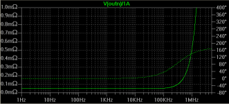
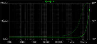
Edit: added the obligatory simulated output impedance plot, the first image. The second image is the simulated output impedance plot of a lower power shunt regulator, that's still in the works.

Positive and negative versions of v2, for 15V out, about 350mA load, another 350mA goes through the shunt mosfet. All using n-channel mosfets, one can use different mosfets than what I show here, with little change to the schematic.
Comments on the positive one will apply to the negative version as well. J3 and R7 set a mini-CCS so the voltage drop across R2 biases M2. Do not take the value of R7 and R2 as given in the schematic more than a rough approximation. You'll have to find the value that gives you the correct bias so that you have the desired total current limit. I like to choose R7 for a current of about 500uA going through the mini-CCS. This depends on the Idss/pinch-off voltage of J3. I hook up J3+R7 to a 9V battery and choose an R7 that gives me 500uA.
R6 is not necessary, I use it to measure the current through the shunt mosfet M1. I think of this current as "reserve" current, which is used to do the needed regulation as more or less current is drawn by the load.
Assume that the Idss of jfets in this schematic is between 7 and 8 mA.
It's very important that Q2 and Q3 are RF transistors.
Take the value of C2 only as an indication. The ideal value is no cap at all, but start low and go up if the regulator oscillates. Or start with a 100uF and then go down until it starts oscillating. Then go back and use the last value that did not oscillate.
Use whatever references you want instead of the zeners. If you use zeners, our best results were with a 1000uF cap across them. Don't go crazy there because the inrush current with a huge cap will fry M2.
I have built a version very similar to this (positive only), which worked well for 20V out, and up to about 3-4A.
If anyone builds it, please let us know how it went.
Ask questions if you're stuck.
Edit: added the obligatory simulated output impedance plot, the first image. The second image is the simulated output impedance plot of a lower power shunt regulator, that's still in the works.
Attachments
Last edited:
ok! thank!
but I want V- out +- 5v for my DAC, not +- 15 v!
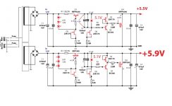
You can share for my one circuit Standard out put +- 5V,! or +- 5.5 V
thank you very much!
but I want V- out +- 5v for my DAC, not +- 15 v!
You can share for my one circuit Standard out put +- 5V,! or +- 5.5 V
thank you very much!
quanghao, the circuit I posted was not meant as an answer to you, it was for someone else. But you're welcome to build it if you'd like, for 15V. It cannot be easily modified for 5V out.
quanghao, you need to choose two LEDs (colour does not matter) and test with a 9V battery what voltage they will drop. Use some 300 ohm resistor in series with them. In the real circuit you can use a 1k trimmer resistor in series with two LEDs. Then adjust the trimmer until you get the correct voltage out.
1k in series will add much. 10% of the trimmer will be usuable. Not handy.There are 5-6mA running there for average BL grade Idss under 0.6V Vbe. Not as much as under 9-10V Idds test, but potent enough for 1k. Maybe 2X1.8-2V Leds plus 100R trimmers if for a partially adjustable Led-res combined 5V Vref.
the circuit I posted
Nice one Iko, BTW. Takes some rather experienced builder and an oscope will be handy non the less.
Nice one Iko, BTW. Takes some rather experienced builder and an oscope will be handy non the less.
Thanks salas. Yep, I think so too, it's not exactly a beginner's circuit. If anybody would like to build it, I'll be around to help.
Here's some tests done on zener noise that may be of interest (apologies if already seen) http://www.diyaudio.com/forums/showthread.php?threadid=35821
I'm going to build a V1 to power my Tripath (TA2020 100Watt amplifier) and compare it to a bipolar series Vreg that I just built based on IRF9240 & complimentary Mosfets. Will post comparisons here!
I'm going to build a V1 to power my Tripath (TA2020 100Watt amplifier) and compare it to a bipolar series Vreg that I just built based on IRF9240 & complimentary Mosfets. Will post comparisons here!
Go for it!
Good reminder about he noise measurements. As far as the zener noise in v1, salas mentioned it before, you can use other vref devices; LEDs in series, tl431, choose what you like. The measured noise for me with a zener+1000uF cap was below 100uV at the output, if I recall correctly.
A word of warning about those measurements. They are very good for ranking components. The moment you put that component in the circuit, it's the noise that makes it to the output that matters. In some positions, a very low noise vref can end up being amplified and you end up with noise on the output that is of unacceptable levels. Similarly, a fairly noisy vref can be use in such way that most of the noise is filtered and doesn't make it to the output.
Just my 2c
Thanks Iko,
I just got back from the bench but progress wasn't nearly as fast as I had hoped - some problems with the series vreg which turned out to be a reversed TL431, doh!
Anyway, I didn't get to build the shunt reg yet. Any help on putting a TL431 in the shunt instead of a Zener (I don't think I have any 12V zeners or 20V zeners for that matter). I thought it would have two advantages:
- possibly lower noise than the zener (your comments above might apply)
- the ability to adjust the Vout via a pot or trimmer
The series Vreg uses a TL431 as Vref so it would possibly allow a fairer comparison between the two regs & it would allow me to adjust the Vout between 12V (for Tripath) & 19V (for Laptop)
Put a 3k3 resistor exactly as a zener in the shunt. That must take you roughly at 20V. About 2k for 12V. Depends on particular jfet, measure vout. Then you can fine tune values. The TL431 is going to be more noisy over its 1mA best with 5-6mA that the jfet will run it. Just a resistor has a better chance there IMO, and you gonna install in a blink.
- Status
- Not open for further replies.
- Home
- Amplifiers
- Power Supplies
- The simplistic Salas low voltage shunt regulator