I cant' see! Thanks anyway! If you want me to see attach picture or schematic or both. Happy that you like!🙂🙂🙂
Listen, when you post, if you look down, it says ''Additional Options''.
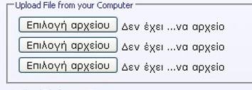
There is a button that says ''Manage Attachments''. There you attach pictures. OK?
Attachments
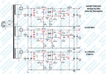
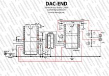
Aha! Very nice drawings! Are you a professional? Do you have a picture of the DAC & shunts working? What do you like so much in its sound?
You like simple like me. Do you like tubes and open speakers too? In what system are you listening to the DAC + shunts?
You like simple like me. Do you like tubes and open speakers too? In what system are you listening to the DAC + shunts?
Yes, I like simple!
I like the tube, but not sound like too open to
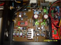
When I use my shunt see:
Quality sound better, more stable and more solid
Larger space, free work transparent, clear!
I like shunt regulator for My system !
Thank you again!
Hi Guys,
if i want built salas shunt for my dac, can i use a irf610 as mosfet and what's current for CCS mosfet and shunt mosfet? Thank you! Maxpou
if i want built salas shunt for my dac, can i use a irf610 as mosfet and what's current for CCS mosfet and shunt mosfet? Thank you! Maxpou
Current you set at 150mA with 15R R1 2-5W, and check if it is enough for your 5V needs. IRF610 OK for negative, IRF9620 OK for positive. Use 2X Led instead of zener, that show 2.2Vf at about 5mA. Vinput 10-12V DC.
Hi Guys,
if i want built salas shunt for my dac, can i use a irf610 as mosfet and what's current for CCS mosfet and shunt mosfet? Thank you! Maxpou

Greek predates Latin, and lends to Russian alphabet (Cyrillic). Former Eastern Bloc people learn the language and read it very fast. Latin based mother tongue people are very slow in picking it up. Romanians & Italians are the fastest among them though.
You look for a cartridge transformer? Will start a tube phono for sure? Make the Phono Dude. And mix in a simplistic HV shunt reg while you are at it.😀
You look for a cartridge transformer? Will start a tube phono for sure? Make the Phono Dude. And mix in a simplistic HV shunt reg while you are at it.😀
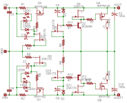
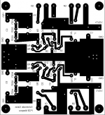
While waiting for some very important parts, I have been working in the pcb for the V1 with sense wires.
This is my last effort after some of your comments.
Please let me know if you agree with this layout... (Hope I can bend the legs of the mosfets even after placing the heatsinks🙄)
Ricardo
This is my last effort after some of your comments.
Please let me know if you agree with this layout... (Hope I can bend the legs of the mosfets even after placing the heatsinks🙄)
Ricardo
Attachments
While waiting for some very important parts, I have been working in the pcb for the V1 with sense wires.
This is my last effort after some of your comments.
Please let me know if you agree with this layout... (Hope I can bend the legs of the mosfets even after placing the heatsinks🙄)
Ricardo
Looks good to me Ricardo. I see no reason why you shouldn't be able to bend the mosfet legs.
Here are a few suggestions, nothing terribly important.
* make the mosfet pads so that there is more copper around the hole; the hole can be a bit smaller diameter, the the pad can be made oval (like eagle does), so that it is extended towards empty parts of the board. When it is circular and you make the pad wider in all directions then it gets too close to other tracks
* make the track from +vin to the 10R resistor as thick as the rest of the main signal track
A general suggestions; try to use C4, the output cap, as small as you can get away without oscillation. Ideal would be to have no cap there.
Thank you Iko
I will review the layout and post again.
What would be the minimum cap value in C4 ?
Ricardo
I will review the layout and post again.
What would be the minimum cap value in C4 ?
Ricardo
Thank you Iko
I will review the layout and post again.
What would be the minimum cap value in C4 ?
Ricardo
Do you have a way to tell if it oscillates? If so, then try without any cap there. If its stable, see how you like the sound. If not stable or you don't like the sound, try 10nF, or 47nF, or 100nF, or 470nF, or 1uF... and so on. You're a master tweaker, I expect that you would find the best that works for you; let us know too, your impressions.
Just to explain, there are some experienced people who think that the reason a shunt reg sounds so good is because it decouples (separates) the psu capacitors from the circuit it powers. The output cap on the regulator doesn't have much of a reason besides helping against oscillation. So, if the reg doesn't oscillate without the cap, it should be most transparent solution. Otherwise, smallest best cap you have would be recommended. But you're much more of a tweaker than I, so please test and let us know.
Hi Salas !
I have a job I would ask him to help!
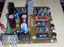
In may DAC shunt supply
Vinput 10-12V DC.
I replaced Diot July 4.7 v = 5.1v
both negative and positive source of real results are:
+ out 5.5 v to the right!
- different a larger capital May 5.9 v!
Please ask how to adjust to negative and positive with each other!
thank you very much
Pm you can see the image!
I have a job I would ask him to help!
In may DAC shunt supply
Vinput 10-12V DC.
I replaced Diot July 4.7 v = 5.1v
both negative and positive source of real results are:
+ out 5.5 v to the right!
- different a larger capital May 5.9 v!
Please ask how to adjust to negative and positive with each other!
thank you very much
Pm you can see the image!
Attachments
Hi ikoflexer!
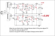
What do you think when I change Zenner diot 4.7V by one adjust????
An what the value of adjust?????
Good or not good???when use adjust change zenner diot???
Because supply + and - out is not the sample!
Thank!
What do you think when I change Zenner diot 4.7V by one adjust????
An what the value of adjust?????
Good or not good???when use adjust change zenner diot???
Because supply + and - out is not the sample!
Thank!
- Status
- Not open for further replies.
- Home
- Amplifiers
- Power Supplies
- The simplistic Salas low voltage shunt regulator