By the way, is high Q (ringing at start up) LC PSU filter harmful for sonics, considering, the shunt draws a constant current?
The scope probe is connected parallel to the choke here (voltage ripple on the choke). This is the BJT regulator for the digital 5V.
The scope probe is connected parallel to the choke here (voltage ripple on the choke). This is the BJT regulator for the digital 5V.
Attachments
Last edited:
Thanks! Although question 1 about the board with the existing regs doesn't remain clear to me.
Leave the 47uF as terminal. Since regs expect a capacitor before them it should be alright.
post6660
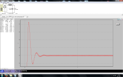
The right pic shows approx 75mVpp of ripple in the psud2 simulation.
How does that compare to the measured ripple of the actual PSU?
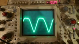
What is the ripple value in the middle pic?
Note how "rounded" the bottom of the ripple is. This is the effect of more HF filtering due to the choke/Inductor.
The right pic shows approx 75mVpp of ripple in the psud2 simulation.
How does that compare to the measured ripple of the actual PSU?
What is the ripple value in the middle pic?
Note how "rounded" the bottom of the ripple is. This is the effect of more HF filtering due to the choke/Inductor.
post6661
The LF oscillation is poor and in my view needs attention.
By the way, is high Q (ringing at start up) LC PSU filter harmful for sonics, considering, the shunt draws a constant current?
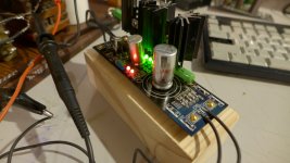
The scope probe is connected parallel to the choke here (voltage ripple on the choke). This is the BJT regulator for the digital 5V.
I don't like the overvoltage on start up.Better damp it with some resistance in series to the choke I would think.
The LF oscillation is poor and in my view needs attention.
I dampened the choke with 10R in series. There is no further ringing now.
Andrew, the scope readings match the PSUD simulation with 90mV p-p ripple.
Regards, Alexander.
Andrew, the scope readings match the PSUD simulation with 90mV p-p ripple.
Regards, Alexander.
That's good agreement with what I could read off your Psud2 pic............... the scope readings match the PSUD simulation with 90mV p-p ripple.........
It's nice when sim = actual.
So, to summarize:
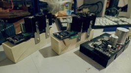
I've built 3 Salas blb 1.1 positive boards for my dac and they are:
-A 5V BJT version for the XMOS board, clock PSU, dissipating at 310mA (the board needs 200mA). It has 47uF Elna Silmic II at the output, R107 shunted. C104 is Elna Silmic II 220uF, bypassing 2 red leds and 160R metal film. C101 is Panasonic FC 2200uF locally. It is preceeded by a 100mH choke and ringing is tamed by 10R in series with the choke.
-A 4,75V BJT version for the Xmos board, general part PSU, dissipating 564mA (the board needs 400mA). It has 47uF Elna Silmic II at the output, R107 shunted. C104 is Elna Silmic II 220uF, bypassing 2 red leds and 100R metal film. C101 is Panasonic FC 2200uF locally. It is preceeded by a 100mH choke and ringing is tamed by 8R in series with the choke.
-A 8,5V MOSFET version for the TDA1543 ICs, dissipating 1A. The ICs needs about 700mA. It has 47uF Elna Silmic II at the output, R107 shunted. C104 is KEMET/RIFA PEG 150uF, bypassing 2 red leds and 909R metal oxide. C101 is KEMET 22 000uF locally. It is preceeded by a 100mH choke, no damping resistor needed.
-All supplies are choke input
I have a few more questions:
-Should I try going Zobel output for the analog part? I have a Mundorf audiophiler cap 4,7uF
-How should I proceed with the C104 decoupling capacitor. Aren't my resistor values too low to be decoupled by a film capacitor? 100..150R needs a hell of a value decoupling cap, or,
-should I replace the leds by a whole big resistor, to cut on the decoupling capacitor value, or
-should I try putting leds only and have no capacitor, otherwise, what is best for analogue power supply?
C104 is not a decoupling condenser but a series capacitance to R107 together forming a Zobel termination. When utilizing the C103 47uF lytic position you jumper R107 since it has enough ESR and gives earlier open loop gain phase turn due to its 10x vs C104 value. When deciding to compare C104 you install R107. Wider reg bandwidth as when with Zobel is usually more pleasant on line level analogue but its mostly a matter of synergy in each application. You got to test and form an opinion in a certain configuration.
In C101 (201, 301) case, when using low impedance in the Vref, you can use say 1000uF even (which is not that fat a cylinder in low voltage lytics).
I wrote wrong capacitor labels. I ment C101, not 104 🙂.
I will then try the Zobel after building the DAC and listen a bit. My system's a bit on the sleep side, it needs some kick.
Here are some photos:
I will then try the Zobel after building the DAC and listen a bit. My system's a bit on the sleep side, it needs some kick.
Here are some photos:
Attachments
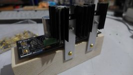
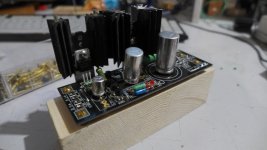
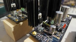
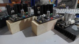
Did you buy those capacitors without any insulation/damping/thermal conductor?
Or did you remove the coating yourself?
Put the wrap back on.
Or did you remove the coating yourself?
Put the wrap back on.
Vgs(th) must not be more than 3V in those 3055E units that you will select and your V(out) must not be less than 5V in order to have space for the mirror's 2Vbe to squeeze in.
- Status
- Not open for further replies.
- Home
- Amplifiers
- Power Supplies
- The simplistic Salas low voltage shunt regulator