That could well be.
Based on what y'all have said, if I build screen reguators, I should be able to adjust the cathode current, but will probably need to change the cathode voltage source as well.
I'll up the cathode bias voltage source to 10V and should hit 50mA of plate current around 220V on the screen based on this data sheet I've been using (or ignoring as the case may be).
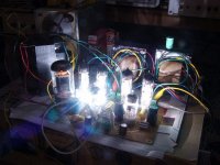
Attachments
Well, I thought I posted a long dissertation about testing with RLD bias, LED ref Vreg bias, zener bias, and cathode bias, but the post apparently contained majik smoke that got away.
Basically, low screen voltage was my problem. All four bias methods worked well. I drove the plate current up till I could hardly see a feint glow to the seam of one tube in the dark at 14.75W plate dissipation per tube. Stout little buggers.
The amp has been running fine all evening.
Back to documentation of what I've done.
Next will be adjustable screen supplies, I didn't make it out today at lunchtime to buy the parts I needed so it will wait till I get the parts.
I'll take this back to the 6P1P thread since it will diverge from RLD bias now.
Thanks all.
SY,
I have my RLD singing for me for almost 2 years now.
Lately I open it up and recheck all the voltage to make sure everything is working ok and I found couple problem hope you can tell me how to make it work right.
1). The Maida screen supply ( direct copy from the schematic provided ) can't be adjusted to desired voltage, but only working between 298v to 320v. I double check there is nothing burnt. Can I lower the value of the 56K 3w and or other resistor ?
2). The output tubes on one channel seems working not properly, one of the tube obviously shows dimmer than the other one. Is it the result of aging after heavily use? and is it possible to put a balance pot in between the two cathode to make the adjustment?
Thanks in advance
Albert
I'd replace the output tubes. The JJs I was using still seem to be singin' along, but I can't vouch for the longevity of others. I didn't find a need for this, but you might want to put a 1k resistor in series with the screens to get longer life. For balancing currents, use separate regulators- they're cheap and compact.
If your adjustment range on the screen supply is that small, you probably DO have something burned. Check the pass transistor for collector-to-emitter shorting. If that's the case, both it and the 317 should be replaced. Also check the zener.
If your adjustment range on the screen supply is that small, you probably DO have something burned. Check the pass transistor for collector-to-emitter shorting. If that's the case, both it and the 317 should be replaced. Also check the zener.
If your adjustment range on the screen supply is that small, you probably DO have something burned. Check the pass transistor for collector-to-emitter shorting. If that's the case, both it and the 317 should be replaced. Also check the zener.
...and when you put it back together, make sure that the pass transistor and lm317 are heat sinked (insulated too). I find it helpful to keep things like zeners mounted above the board so that air can circulate -- when a zener dies it goes short (like a tantalum cap) and it can cause a cascading series of events.
Turkish names can be like that. One of my colleagues used to visit a Turkish appliance company with a name whose English sound-alike you wouldn't utter in polite conversation. The department secretary he dealt with had a last name of the same mentioned in that letter referenced here....
On to business. I'm thinking of doing a version of this amp with a discrete shunt regulator replacing the LEDs (The No-Light District!) SY and I have discussed the implications of using solid state vs. passive (relatively speaking) biasing, and I thought it would be time to test the concept in an amp similar to his. I have had the solid state bias regulator working in a low power SE amp ("Mighty Mite") for some time, with good sonic results.
Anyway, I was thinking of using a 6JK8 for the front end, with the high transconductance half in front, and the humbler triode of the pair as phase splitter. I have two divergent paths to follow for output stages, based on choice of output iron. I have a couple of sets of output transformers taken from Baldwin organs. One set is 6k p-p into 8 ohms. I would use these with 6P14P-EV or 6JB5. The other set is 6k into 16 ohms, and I was thinking of using them with 6CW5 or 6HB6 with lower B+, into an 8 ohm load. Comment on what you think is a better approach for the outputs, and I will split it off into another thread. I think I really will call the amp the :"No-Light District".
PP 6CW5 (EL86) at 250V (200V Screens) will give you 25 Watts into 3K Raa (8 Ohms load on 16 Ohms tap of 6K:16 Ohms OT). Will the trannies handle that power? The concertina splitter may be marginal at low B+ but you only need to swing 34V pk-pk at the output tube grids. Bias is -18.5 Volts.
Cheers,
Ian
Cheers,
Ian
The transformers were supposedly paired with 6L6s in their previous life. No taps, just the one secondary. The 6HB6 would also be an ineresting pairing. These have an extremely high transconductance , so they would easy to drive. They consequently way also be difficult to stabilize, but not everything worth doing is necessarily easy...
I'm thinking of doing a version of this amp with a discrete shunt regulator replacing the LEDs (The No-Light District!).......Comment on what you think is a better approach for the outputs, and I will split it off into another thread. I think I really will call the amp the :"No-Light District".
OK, bring on the new thread. I have an NLD operational on my workbench. I wasn't quite ready to spring my new secret weapon on the world yet, but here are the details on the experiments so far. Feel free to move this post to your new thread. Some details are also in my Simple P-P thread. One builder of a Simple P-P board has already added red LED's to his amp.
http://www.diyaudio.com/forums/tubelab/148694-tubelab-simple-p-p.html
I am building a new amplifier that will look very "different". I am sure that it will look ugly to many traditionalists, but I am tired of making "tubes and transformers on a metal plate with wooden sides" amps. This one draws its cues from a variety of non traditional objects, including some photos I took of blinged out import tuner cars at a recent show. There will be pictures when I finally finish it.
During the development of the Simple SE I tried the LED bias approach suggested by SY. I found some white LED's that were used as the flash in a camera phone and wired 3 of them in series and placed one string in the cathode of each output tube. The sound quality improved (bass and transients were better) and the output power went up. What's not to like. Well, at least in my case there is just too much light. My new amp uses two Simple P-P boards each wired in PPP for a two channel amp. This makes 8 EL84 tubes, each with 3 to 7 LED's.
I have been conducting some experiments on my Simple P-P boards. The camera phone LED's are surface mount, and I only had a few of them, so I started searching for something else. The Simple P-P builder used Fairchild MV50152 LED's, but they aren't in stock anywhere. I went through the digikey catalog and ordered a few different LED's based on their calculated dynamic resistance. It seems that 3 to 5 ohms per LED is typical. A series string could have from 10 to 40 ohms. I didn't want to order 50 LED's yet until I tested them.
I also ordered a few parts to make a "CVS" circuit. What is a CVS? Well, it is an anti CCS, a Constant Voltage Sink. A perfect CVS should be like a perfect zener diode. The voltage across the device should remain constant regardless of the current through the device. It would be really cool if you could adjust the voltage with a twist of the screwdriver too. It is possible to make such a circuit with an opamp and a pass transistor, or it can be built entirely with transistors, but there is a better way. How do you make the mythical CVS? It is too easy. Look at the attached data sheet and turn to page 7. Figure 13 is what you need. Just eliminate the Vi terminal. Connect the bottom terminals to ground, and Vo to the cathode, adjust the pot for desired tube current.
Preliminary tests of the CVS reveal a dynamic resistance of way less than 1 ohm. Unfortunately I only got enough parts for 2 circuits (and I blew 1 up), but stuff for 20 more are on their way. The LM431 is specced for up to 36 volts and up to 100 mA. It will NOT do both at the same time, even if you mount it on a heat sink. How do you think I know this! The transistor should be a decent quality device with good beta. I wanted to use a row of shiny steel 2N3055's that I have had since 1969, but they didn't work as good as the little junk box TO220's that I used.
More science when the next Digikey box arrives.
Attachments

What about a Vbe multiplier?
That is what I meant when I said "or it can be built entirely with transistors". I should have said transistors and resistors. The VBE multiplier works. The chip has a lower dynamic resistance (specced at 0.2 ohm). The chip with an external pass transistor is higher than 0.2 ohm, but less than 1 ohm. I will make more detailed measurements when I get more chips.
Ahhh, sorry 🙂
What about a darlington Vbe multiplier, I bet that would have a super low impedance....
What about a darlington Vbe multiplier, I bet that would have a super low impedance....
George,
What would constitute a "good" CVS for this application?
Low "stall" current?
Fast recovery from "stall"?
Low Z?
Low feedback?
It struck me that there are a dozen CVS drawings in the Shunt Wiki but they were not necessarily suitable / optimum in this application.
Shunt Regulation - diyAudio
Doug
What would constitute a "good" CVS for this application?
Low "stall" current?
Fast recovery from "stall"?
Low Z?
Low feedback?
It struck me that there are a dozen CVS drawings in the Shunt Wiki but they were not necessarily suitable / optimum in this application.
Shunt Regulation - diyAudio
Doug
I use the TL431 all the time at my job, but did not consider it seriously for my voltage source because of its limited voltage rating and its habit of wonky modes of behavior when confronted by RFI. I decided I wanted all the circuit elements out where I could see and control them, and designed a voltage source using 3 transistors and a mosfet (4 transistors if I use a reverse BE junction as reference) that can be scaled to any reasonable voltage and current level I desire.
You can see an example of the circuit in my "Mighty Mite" thread. In that circuit, a TL431 was used as a reference (with reference pin connected to anode) for its low idle current requirement, but I've made that go away.
You can see an example of the circuit in my "Mighty Mite" thread. In that circuit, a TL431 was used as a reference (with reference pin connected to anode) for its low idle current requirement, but I've made that go away.
What would constitute a "good" CVS for this application?
Well, first lets examine what we are trying to replace. In a cathode biased amp there is a resistor and a capacitor in parallel from one or more cathodes to ground. The capacitor attempts to provide a low impedance to ground for all AC frequencies of interest. The resistor provides the bias voltage for the tube and incorporates a built in operating point stabilizing feedback.
If we remove the RC network and substitute it with an ideal voltage source (zero output impedance) we have done two things. We now have a zero impedance path to ground for all AC frequencies, and we have a fixed bias point that does not change with drive level or overload. The bias stabilizing feature provided by the resistor is gone, and we now have essentially a fixed bias situation. This allows pushing the tube harder without bias shift. The G1 resistor should now meet fixed bias specs to avoid grid current related runaway.
Now we can't get ideal voltage sources from Digikey, so we would like to make something that is as close as possible. What "ideals" are important to us?
You mention "stall current". The chip in this design, or the discrete components in the designs you linked to all require a minimum current to operate. This is the "stall current" if you connect a CVS to a single tubes cathode and that tube is in cutoff this current will not be provided so the CVS will stall. A finite recovery time will be required to restart. This condition must be avoided. As with LED bias, the solution is simple, a resistor from one of the supplies is used to provide a bias current that is greater than the stall current. Another option exists too. It is possible to run one CVS to both tubes in a P-P pair since one will always be conducting, thus eliminating stall current issues, but matched tubes may be required. I tested this, in fact I wired all 8 tubes to the same CVS and it worked reasonable well.
Low Z is important. In fact it is the reason for doing this. Ideally we want a zero output impedance for all frequencies. In reality the output Z will increase at the frequency extremes.
You also mention low feedback. Feedback is usually the method by which low Z is provided.
I have also tested a rather "dumb blonde" circuit with no feedback that sounded surprisingly nice. My amp uses 2 Simple P-P boards. I simply wired the filament connections to each board in series. One end of the series connection was grounded and the other end was connected to a DC supply made by series connecting the two filament windngs on the Antek toroid, a bridge rectifier and a big cap. I used a big resistor (about 1/2 ohm) to drop this to 12.7 volts. I simply connected this 12.7 volt source to all 8 cathodes (and the series connected filaments). Total filament current is 3.6 amps, so the effective Z was about 3.5 ohms.
More experimentation will determine whether feedback in this circuit makes any difference.
It struck me that there are a dozen CVS drawings in the Shunt Wiki but they were not necessarily suitable / optimum in this application.
I did not know about that wiki but I have tried many of these circuits. I simply Googled for terms like "adjustable zener diode" and "VBE multiplier". Some of those circuits do directly apply here, but it is too soon to tell where the optimum performance VS simplicity point will lie.
- Home
- Amplifiers
- Tubes / Valves
- The Red Light District - another PP EL84 amp