As with LED bias, the solution is simple
Except you don't need that with LED bias, since the turn-on time is so fast. It might be useful for linearizing the dynamic resistance against current change, but at the scale of an output tube cathode (and especially in push-pull), that's pretty minuscule. It won't hurt anything, but it won't really help anything, either.
What I like about the electronic vs the LED solution is the possibility of easily dialing in the required bias voltage, also the circuitcan be more physically compact. Check the size of the "Mighty Mite" amp in that thread - there are two biasing arrays in that tiny case, along with an SMPS.
Anyway, as this discusion it heating up and starting to draw posts, it may be wise to split this thread off so it runs no danger of diluting SY's original intent. Stuart, what do you think? If split off, I suggest we call it the "No Light District" P-P Ampifier, harking back to its origin...
Anyway, as this discusion it heating up and starting to draw posts, it may be wise to split this thread off so it runs no danger of diluting SY's original intent. Stuart, what do you think? If split off, I suggest we call it the "No Light District" P-P Ampifier, harking back to its origin...
You know me- eclectic, wishy-washy, and tough to offend.😀 If you want it here, fine, if you want a new one, fine.
As long as you don't mind, ok. However, if the thread starts getting "No Light" top-heavy, you have the option - just say the word.
I just realized I already have a perfect test bed for the No-Light concept. I have a Lafayette LA-234 integrated amp that uses 7189 outputs. The innards were probably built by someone like Pioneer or Trio. I have always intended to gut the interior, as the circuits used were somewhat uninspired, and replace them with something completely different, even though the outward cosmetics will remain the same. This would be a perfect platform for doing a No-Light power amp using 6P14P-EV output tubes, with the aforementioned
6JK8 for input and phase splitter. Since I've had worries about being able to supply the needed filament power with the original power transformer (many of the tubes I want to use draw more filament current than the originals), I've already decided to ditch that XFMR in favor of a custom SMPS, so the thing will be almost a complete impostor under the hood.
The No-Light biasing scheme will be easier in theory with a P-P as compared to a single-ended amp, as at no time will there be any interruption in current through the bias circuit. When one output tube is in cutoff, the other is being hammered. With the Mighty Mite, I had to take a lot of pains budgeting current draw and providing an extra bias resistor to keep the bias circuit active when the output tube is driven into cutoff. You don't want to have any wonky behavior when the amp is recovering from overdrive. I also did a lot of simulations to ensure that the transient response would be clean and fast. Since the Red Light District limits the bandwidth of the input stage, this may make design of the bias circuit less critical
I've always meant to look at the response of the bias circuit in the Mighty Mite under heavy square wave drive, but have never gotten around to it. Maybe it's time. If I do, I'll post results here.
It always comes down to that. 🙂Now we can't get ideal voltage sources from Digikey, so we would like to make something that is as close as possible. What "ideals" are important to us?
You mention "stall current". The chip in this design, or the discrete components in the designs you linked to all require a minimum current to operate. This is the "stall current" if you connect a CVS to a single tubes cathode and that tube is in cutoff this current will not be provided so the CVS will stall. A finite recovery time will be required to restart. This condition must be avoided.
As with LED bias, the solution is simple, a resistor from one of the supplies is used to provide a bias current that is greater than the stall current.
 Simple once you say it.
Agreed.You also mention low feedback. Feedback is usually the method by which low Z is provided.
Agreed.More experimentation will determine whether feedback in this circuit makes any difference.
My first guess is that anything that is << 10% of the cathode resistor is "good".Low Z is important. In fact it is the reason for doing this. Ideally we want a zero output impedance for all frequencies. In reality the output Z will increase at the frequency extremes.
I wrote the Wiki so I could talk to my Brother about it. The responce was in russan. It didn't translate well. 🙂I did not know about that wiki
My guess is that it probably depends on how low an impediance really makes a difference.Some of those circuits do directly apply here, but it is too soon to tell where the optimum performance VS simplicity point will lie
Thanks.
Doug
With a discrete regulator of not too many components, output impedances in the tens of milliohm range are readily obtained, with stable and ultra-fast response. The TL431 has a basic dynamic impedance of about an ohm. However, I cannot tell you the bandwith over which that is valid. Amplifying the 431 with an external transistor will lower the output impedance.
The simplest impllementation of a 431-based regulator I'd consider for a P-P amp would be a 431 with a PNP Darlington pass element. This allows one to run the TL431 at a reasonably low bias current to limit power dissipation, and also to make it easy to drive the pass transistor. This is especilly important with a push-pull amp as the regulator can be froced to swallow substantial amounts of current if the amp is driven hard. The cathode load resistor of the 431 should be adjusted for enough bias current to satisfy the minimum requirements of the 431 without substantially turning on the pass transistor. This should be 1-1.5mA, as the "maximum minimum" bias current in the TL431 data sheet is 1 mA. Adjust the load resistor at the cathode so that there is enough voltage drop at the current of interest to barely turn on the Darlington, say 1.15V. This gives you about 750 ohms for the cathode resistance. 47-100 ohms in series with the Darlington base is also a good idea. Alternatively, one could use a P-channel mosfet as the pass element, though the gain would not be as high. Placing a resistor between the darlington base and the TL431 cathode can be done to reduce power dissipation in the 431 if you need a higher output voltage. It will also give you more impendance to work against if a compensation capacitor is used.
One thing to also consider, is there are a lot of people making TL431s these days, and they don't all work quite the same. I've had good luck working with the National version of the part over the years.
The ground bus bar has pretty low impedance. 🙂 I'm starting to lose sight on the advantages of this versus fixed bias. The negative supply?
Well, you can do fixed bias with source/cathode follower drivers, and that is one route (albeit complex) to decent overdrive behavior. The other is cathode bias, and the active/led approach provides the ultimate in stiff catode biasing. Or you can do things the same old same old, and try not to notice the warts...
I'm starting to lose sight on the advantages of this versus fixed bias. The negative supply?
You got it. The Simple SE and the Simple P-P are "simple" because complicated things like negative bias supplies are eliminated. Cathode bias also allows freedom from bias adjustments over a reasonable range. It also limits the maximum power under steady state conditions. Why? If a cathode biased amp is pushed to the edge of (or into) clipping continuously the output tube or tubes will draw more current. The extra current will cause the cathode voltage to increase as the bypass cap charges. If the input signal is suddenly reduced the amp will distort until the cathode voltage returns to normal. This should not occur with normal music and a correctly sized bypass cap.
A CVS of some sort in place of the cathode resistor fixes this problem. It doesn't solve the blocking distortion due to the grid cap, and it may make DC stability in the output stage worse. An adjustable CVS in each tube allows bias adjustability and is nearly like fixed bias without the negative supply. Initial listening tests seem to point to better dynamics, but I really need to do a lot more testing.
I started out with a Simple P-P board with the two channels paralleled and got 32 watts with the B+ at 355 volts. This is about what is expected from 4 EL84's in PPP with a 3300 ohm load.
Separating the screen and plate supplies allowed optimizing each voltage individually for more power and lower distortion. For this to work the screen supply needs to be regulated. Bye bye Simple. In keeping with the bling theme I used 3 VR tubes and a simple mosfet follower for the "regulator". It works good. I set the screen supply at 330 volts and the plate supply at 425 volts. Yes, this is far beyond the published ratings for the EL84 and wimpy tubes need not apply, but the JJ's seem OK so far. Power output is 54 watts at 5%. I noticed that the cathode voltage at idle is 12.5 volts. At 54 watts it is 15 volts. Driven to hard clipping the cathode voltage rises to 16.5 volts.
Digging further in the quest for power, I tried several methods to clamp the cathode voltage at 12.7 volts, including the previously mentioned heater supply, the CVS, some LED's, and even ordinary zener diodes. All of these methods resulted in more power at reduced distortion. The best method was the heaters running off of a regulated bench supply. This resulted in 62 watts of power at 5% distortion, 58 watts at 1.1% and 50 watts at 0.711%.
Clearly some power and reduced distortion can be found at the expense of simplicity.
One thing to also consider, is there are a lot of people making TL431s these days, and they don't all work quite the same. I've had good luck working with the National version of the part over the years.
The parts that I had were National. I have some more Nationals on order from Digikey. It takes 6 to 8 days for UPS to get parts here from Digikey, so I ordered some more stuff from Mouser today including a few more LM431's Mouser only has Fairchilds. I got some other parts for other experiments, but On Semi has 5 watt zener diodes with a 2.5 ohm dynamic impedance, so I got some to try also. My last experiment used 4 1 watt zeners in parallel. One was obviously the lowest voltage of the bunch because it got real hot.
Great minds and all...
I imagine this would be a simple brute force approach. Not super-lolw impedance but maybe low enough...
Michael
Ahhh, sorry 🙂
What about a darlington Vbe multiplier, I bet that would have a super low impedance....
I imagine this would be a simple brute force approach. Not super-lolw impedance but maybe low enough...
Michael
Attachments
I'll be simulating (and posting) a couple of discrete cathode bias options, one of which may use a big electrolytic cap to advantage, as opposed to the usual R/C cathode bias approach. The circuitry keeps the cap under control, and vice versa. A lot of this is fallout from some shunt regulators I've been developing for my sand state preamp projects. All are simple enough to put together on a piece of perf board, which is what I did for the bias regulators in my "Mighty Mite" amp.
The TL431 and PNP darlington approach is simple enough for folks who want to try that. I've been working with TL431s for almost 30 years (you're forced to with SMPS circuits as everyone uses them for reference/error amplifier circuits), and I don't really trust them not to flake out/get weird under extreme conditions. To each his own, though.
The TL431 and PNP darlington approach is simple enough for folks who want to try that. I've been working with TL431s for almost 30 years (you're forced to with SMPS circuits as everyone uses them for reference/error amplifier circuits), and I don't really trust them not to flake out/get weird under extreme conditions. To each his own, though.
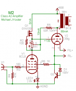
Here is the first in a series of discrete shunt regulators for cathode bias duty. This one is similar to a circuit that I'm using to power a JFET RIAA preamp in the works. This regulator absolutely dotes on a lage shunt capacitance - the capacitor and regulator work synergistically together, resulting in low output impedance and fast, stable response. Just imagine the regulator as replacing the resistor in a traditional RC cathode bias network. Capacitor C1 and resistor R6 represent the capacitance and ESR of a good quality electrolytic - the values were taken from those typical of a Panasonic FM series 100uF, 50V capacitor. The circuit is hammered with a current pulse with a quiescent value of 50mA and a peak value of 20mA, with 10usec rise and fall times. Even George would be hard-pressed to hammer that hard on an amplifier. Simulation results are shown in the next post.
Attachments

Attached here are the simulation results. The DC delta V for an excursion of 50mA to 200mA is 1.05mV. Since the current excursion is 150 ma, the DC output resistance is 1.05mV/150 mA = 7 milliohms. The transient voltage excursion is 1.4 mV, making the transient output impedance 9.3 milliohms.
This is of course a simulation, so that actual results can vary due to actual vs real parameters, and due to implementation (layout, etc). Still, the simulation looks promising. Next up, I'll try eliminating the big electrolytic by using an internal compensation cap.
This is of course a simulation, so that actual results can vary due to actual vs real parameters, and due to implementation (layout, etc). Still, the simulation looks promising. Next up, I'll try eliminating the big electrolytic by using an internal compensation cap.
Attachments
Last edited:
What stall current? This is a P-P amp - current is in place at all times. Or were you proposing to run class C?
Aha, I was thinking SE, not PP.
It would be interesting to see stall current to broaden the scope of the design. It might be suitable for SE as well as PP.
It would be interesting to see stall current to broaden the scope of the design. It might be suitable for SE as well as PP.
Wrenchone, is your q3 buffering your current mirror to the shunt fet? I think it will cause dynamic changes in the loop gain shape and stability margin as the current goes up and down beyond being beneficial on lowering in value and opening in frequency the impedance. Did you simulate the transient without q3?
Well, the circuit I posted first is a bit scary and slippery and probably way higher octane than anyone needs for either SE or P-P applications. This is not to say it won't work, but it's probably ambitious overkill. I was backtracking this afternoon and took a look at the bias circuit I did for my "Mighty Mite" SE amp, which does address your concerns. It clocks in at about 0.5 ohm impedance, which is still better than an LED array, and in a much smaller package. I may throw in a small bone to Stu and post a version of that circuit using a single LED as the bias reference. If I remember correctly, I already posted one in my "Lafayette LA-234" thread. We could call it the "One Light District". At any rate, use the search function to get to the "Mighty Mite" thread (also in the tube section), and you'll see the circuit. Any of these electronic bias options, even the TL431, will need some keep-alive current when used in an SE amp. With the Mighty Mite, I used a resistor from B+ - ugly, but sufficient. I used a TL431 as the voltage reference, as it had a low incremental impedance with only 1 mA of current flowing through it. Since I was using an SMPS that already had a 13V filament supply, I could have used a green or deep red LED instead and given it 10mA or so from the filament supply to bias it up.
Salas - Q3 is a voltage gain element. Of course it will cause changes in the loop gain and stability margin. It also drastically lowers the output impedance. Hanging a largish low impedance cap across the regulator does the trick for stabilizing the circuit. The shunt regulator doesn't allow the cap to charge up during transients, and the cap pads down the HF gain. It's kind of a win-win situation. Fed with a current source, this is the regulator I use for my latest RIAA amp.
- Home
- Amplifiers
- Tubes / Valves
- The Red Light District - another PP EL84 amp