Maybe, maybe not. I've been tryin it in another circuit, and I get weird behavior unless I tone the loop gain way down with local feedback. The impedance is hilariously low as it is.
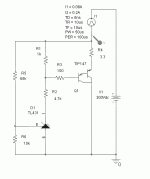
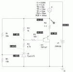
Today I looked at a simulated cathode bias regulator using a TL431 (the model used was from the TI library in PSpice) and a TIP147 pass element (uggish 100V, 10A PNP Darlington in TO-3P package from TI and many others, readily available). The results were surprisingly ok (though I subscribe to Sangamon's principle and don't really trust models of more than a few components). Results were better in simulation without a compensation capacitor.
George - since you brought this one up, it may be useful to hang a probe across your TL431 cathode bias network with AC coupling and catch some waveforms of your amp banging out some square waves. I'll post my simulation results when I get back to work next week, though I will say up front that they looked fairly benign. I'm very interested to see how the real deal compares to the simulation. In the simulation,a lot hinges on how much emitter degeneration resistance you place on the Darlington pass element. It's be a compromise between zippiness and low impedance vs. good pulsed behavior.
For people that don't need a lot of bias voltage (I would draw the line at about 25V or so), this may be a perfectly ok way to go. I reserve judgement a bit, as I want to see how the regulator handles the tube and the transformer leakage inductance.
I have the file and simulation and everything at work, wait until
I get back there Monday - or build it for yourself this weekend (It's simple enough).
I get back there Monday - or build it for yourself this weekend (It's simple enough).
Here is the simulation schematic for the 431 shunt regulator, set for about 20V. The ratio of R1 to R6 adjusts the output voltage.
Attachments
Last edited:
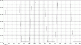
This is the simulated response to a healthy whack in current. Adding compensation in the usual way just screws things up. Keep in mind that this is the response of the TL431 model - the real deal may act differently, expecially under large signal excursions.
Attachments
I just thought I might give a littel update here on my RLD.
I built mine a while back (first major build) and after a few trouble shooting sessions with much help from SY and others here, I got it running.
At the time though, I never had the bias as high as it was capable of, my bias was only ever down around 50-55mA per EL84 pair.
So recently, I took another set of the LEDs out of the string, leaving me with about 8.5V across the string. Then I dropped the screen voltage until I hit about 85mA current (I am using russian 6P14P-EV).
The result is that the amp is more dynamic, but I seem to have still kept the smoothness and elegance of it. In other words, all the positives still apply. I also took the opportunity to replace almost all the audio wiring for silver in teflon type throughout the amp which probably helped a bit too.
Just a quickie update....
Fran
Hmmm, sounds like I need to give those Russian tubes a try.
I guess it depends on which Russian tubes you get. I have some 6P14P (not EV) versions and they will not pass the George test. The JJ's and some vintage 1961 Sylvanias are the only ones that are happy in my latest hot rodded amp. 420V on the plates, 330V screens.
I guess it depends on which Russian tubes you get. I have some 6P14P (not EV) versions and they will not pass the George test. The JJ's and some vintage 1961 Sylvanias are the only ones that are happy in my latest hot rodded amp. 420V on the plates, 330V screens.
I see that Triode has the EV (EB) versions for a reasonable price. I may have to play George for an evening and see if I can kill them.
I see that Triode has the EV (EB) versions for a reasonable price.
I don't see them on their web site. only the 6P14P. I bought some of them from one of the Ebay sellers in the Ukraine. They are good tubes except I can't find any way to get over 15 WPC from a pair without something glowing. I can get 30 WPC from the JJ's without any redness.
Are you qualified for that? In reality I have been subjecting a few Simple P-P boards to some rather extreme testing and I have only managed to kill one resistor since I started playing with them. No melted tubes or exploded capacitors. The same can not be said for the red board though. It's not Petes fault, he never said to run it on 600 volts.
I don't see them on their web site. only the 6P14P. I bought some of them from one of the Ebay sellers in the Ukraine. They are good tubes except I can't find any way to get over 15 WPC from a pair without something glowing. I can get 30 WPC from the JJ's without any redness.
I may have to play George for an evening and see if I can kill them.
Are you qualified for that? In reality I have been subjecting a few Simple P-P boards to some rather extreme testing and I have only managed to kill one resistor since I started playing with them. No melted tubes or exploded capacitors. The same can not be said for the red board though. It's not Petes fault, he never said to run it on 600 volts.
I don't see them on their web site. only the 6P14P.
The web site is indeed ambiguous. On the tube index page, they say that they're the EB version. On the 6BQ5 page, they don't. I'll have to call them and find out.
Are you qualified for that?
I have several floatable 0-500V/1A power supplies and safety goggles. I'm ready to rumble.
Whether the 6P14P-EVs are contenders or blushing hothouse flowers seems to depend on the reviewer. Some praise them for being tough and good sounding (especially if they happen to be selling them). They are certaily the cheapest alternative to NOS 7189 I've seen. I'll be happy if mine hold up at 350V on trhe plate and somewhere near there on the screen - that's currently how my SMPS is set up.
Between SY and George we'll find out if they're contenders. What will glow first - the screen or the plate?
Between SY and George we'll find out if they're contenders. What will glow first - the screen or the plate?
mmmm, I have a little confession....
after reading how excited you guys have got over these valves, I thought I better check them again. Turns out they are not the EV version....
oops!
Fran
(who has 318V B+ and 285 on the screens)
after reading how excited you guys have got over these valves, I thought I better check them again. Turns out they are not the EV version....
oops!
Fran
(who has 318V B+ and 285 on the screens)
I'll be happy if mine hold up at 350V on trhe plate and somewhere near there on the screen - that's currently how my SMPS is set up.
No problem there. My standard Simple P-P runs 360V of B+ which puts about 335 or so across the tubes. Cathode is at 11.5 to 12.5 volts and plate is at 347 volts. Nothing glows even with the $4 Ebay tubes. I get about 15 WPC.
What will glow first - the screen or the plate?
In any of my 6BQ5 - EL84 - 7189 - 7189A - 6P14P experiments the screen always glows first. In fact I haven't made the plates glow yet. I have a test setup with the plates (OPT CT) on one power supply and the rest of the amp (including the output tube screens) on another. For the first round I had 270 ohm cathode resistors in each tube. I bring the plates up to the desired test voltage (I have been to 450V on good tubes). The current draw should be very low. I then bring up the screens slowly while observing the measuring equipment, and the tubes. The allowable screen voltage depends on the tubes and the B+ voltage, but in ALL cases so far the screen grid will glow first.
WARNING!!!!!!! If you perform tests like this you must bring up the plates first and turn them off last. If you apply screen voltage without plate voltage your tubes will be TOAST!
In the second round of testing I got the idea to change the bias current. I am working with two boards, each wired in PPP for a total of 8 tubes. I didn't want to change 8 resistors, and the Simple P-P is cathode bias, so I couldn't wire up a negative bias circuit. For this test I wired all 8 cathodes in parallel and attached them to a 0 to 20 volt supply. The Power supply can source current, but not sink it, so it was loaded with the tube heaters in series parallel (12.6 V). Now I had three knobs to turn, plate voltage, screen voltage, and tube current. This worked great allowing me to record some stellar performance numbers, but I prefer to have individual tube current control, which leads me to where I am now with the CVS circuits.
The parts are all here, but it looks like there will be no new experiments for 3 or 4 weeks.
I've made some discoveries regarding No Light/One Light options for cathode bias - another one of those bathroom circuit scribblings that panned out. Definitely more to come after I finish playing around a bit more in PSpice. Let's just say that lead compensation and selective cascoding, like the Thunderbirds, are go! My amp lineup for this year's BA should be interesting...
I see that Triode has the EV (EB) versions for a reasonable price. I may have to play George for an evening and see if I can kill them.
You may want to try -ER (EP in original, supposedly even more robust than -EV and expected to last 10K hours) - a quad for $24 (+ $10 shipping) at 6p14p-er = 7189 = EL84 QTY=4 - eBay (item 220597258591 end time May-28-10 14:40:56 PDT)
How about an emitter follower with LED(s) as the ref?
The cap actually causes some resonances when large enough, and should be left off or kept very small (1nF).
An externally hosted image should be here but it was not working when we last tested it.
The cap actually causes some resonances when large enough, and should be left off or kept very small (1nF).
- Home
- Amplifiers
- Tubes / Valves
- The Red Light District - another PP EL84 amp


