But looking at this circuit it looks to have infinate impedance. Not zero. What is zero is the loading.
Wrong on both counts I'm afraid. The input impedance is zero, and though it is a virtual ground rather than a literal short circuit, it behaves the same way. The loading is not zero. Its close to it, equal precisely to the value of your cartridge impedance.
At RF, though, I agree that this can all be thrown out the window.
I have vague memories of having a similar experience with hum in some commercial audio gear that changed with the position of people in the room, as they occasionally attenuated the reception of RF signals.
Although ferrite beads can do unpleasant things to the sound, they might be useful to you, especially on the power supply wires.
/R
Phonoclone vs. VSPS-ultra vs. VSPS standard
Hallo together,
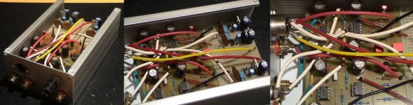
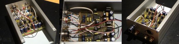
I finished the complete project of all three preamps and will post the results here. It is essential to know, that I didn't use the PCBs from RJM. I used own layouts, all sharing the same power supply layout of regulated 3*7 regulators. I post the pictures here for each preamp separately. Starting with the Phonoclone.
Regards, BSPX
Hallo together,
I finished the complete project of all three preamps and will post the results here. It is essential to know, that I didn't use the PCBs from RJM. I used own layouts, all sharing the same power supply layout of regulated 3*7 regulators. I post the pictures here for each preamp separately. Starting with the Phonoclone.
Regards, BSPX
Attachments

Phonoclone vs. VSPS-ultra vs. VSPS standard
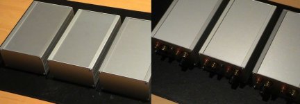
.. and from outside - if someone is interested in. I think there is not too much information in the pictures because the preamps all share the same look - 😀.
Some remarks to the configurations and sound qualities:
1. All Preamps were used with the same 130VA Power supply.
2. All Preamps use the same dual regulation of 3*7 at 12 V.
3. The Phonoclone uses OP27G, Elna Silmic as bypass, Wima as RIAA and black gate as decoupling.
4. The VSPS-ultra uses OP27E, Panasonic FC as bypass, Wima as RIAA and Mundorf as decoupling.
5. The VSPS-std uses MAX437G, Panasonic FC as bypass, Arcotronic as RIAA and generic components as decoupling.
There is a difference in sound quality, which is quite listenable and not subtle. In the above mentioned configurations the phonoclone beats them all, followed by the VSPS ultra and the VSPS standard. The difference between the ultra and the standard is not that much ! All preamps used the same power supply, so the impact of the power supply and regulation to the comparism is minimal. All preamps were run in for at least six hours. All amps used the same cartridge - a denon 103 for the moment.
I suppose, the BIG impact is the OP27G. I will plug and play and switch some other chips in the next weeks and reports the results.
Regards, BSPX
Attachments
Great pictures..
A little sidenote..it really is not possible to compare the Phonoclone with the VSPS is it??..the phonoclone was virtually made for the DL103 while the VSPS was made for your typical MM cartridges.. But nevertheless it was interesting and great that you could do the comparison.
Regards,
Bas
A little sidenote..it really is not possible to compare the Phonoclone with the VSPS is it??..the phonoclone was virtually made for the DL103 while the VSPS was made for your typical MM cartridges.. But nevertheless it was interesting and great that you could do the comparison.
Regards,
Bas
Brainspex, working hard so I don't have to! 🙂
The VSPS can be used directly with low output MC cartridges if you change the loading, R1, to something appropriate and can turn up the volume of the preamp to compensate for the low gain. Not normally recommended.
The only fundamental reason the Phonoclone should sound better than the VSPS is the inverting vs. noninverting topology. The rest is layout, parts, and and other open variables.
As Bas says, though, the designs are not intended to compete with each other ... but rather serve separate niches.
A very interesting experiment, though.
/R
Phonoclone vs. VSPS-ultra vs. VSPS standard
Some remarks:
I pushed the gain of the VSPS standard to 50dB to compete with the ultra and the clone.
"Brainspex, working hard so I don't have to.." Yo, my wife asked already for the reason of 5 little silver shining boxes (2 supplies, 3 amps) in our living area. Me: "It is an experiment !" - smile
I would not see the Phonoclone as a DL103 dedicated design. I had used it already with a shelter 901 successfully, and I think it will match to all low output MC's from 0.1 mV to 0.6 mV.
PCB-Layout: It has an impact, yes. The VSPS-ultra and the VSPS-std got a new grounding layout (seen in the pics). This layout beats the phonoclone in radio interference, noise, hum etc. In fact the VSPS-ultra without the cartridge connected is death silent, as silent that you cant hear anything from the speakers even if the volume is at the right end, like switched off.
Regards, BSPX
The VSPS-ultra and the VSPS-std got a new grounding layout (seen in the pics).
I did notice that the regs part of the same board in the two VSPS designs, closer to the op-amp(s). However its difficult to see from the pictures what the ground routing actually is.
On a side note, the VSPS ultra should not be that much different from the VSPS from a noise standpoint, when something like the OP27 is used for both and the same cartridge is attached. It is, after all, the same circuit and while the input impedances are slightly different they are sufficiently low in both cases that they shouldn't affect the total noise much. (That's assuming R2 in the VSPS is below 1k)
/r
Layout VSPS standard and ultra
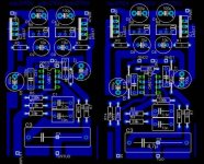
This is the layout of the PCBs of the VSPS standard and VSPS ultra,
there is no suprise so far. It follows the ideas RJM made in this
forum too. The size is always a half standard Euro PCB
size. Schematics and Layout were made with EAGLE - a fine tool !
Hints: cable-bridges were made as resistors. Some values of resistors were changed later.
- Regards, BSPX
Attachments
Thats a cool looking triple🙂 Good work.and from outside - if someone is interested in
Steen😎
Ground loop or RFI?
I completed my phonoclone but there was hum sound. Powered up the amp and phonoclone only and turnned the passive preamp volume up all the way hum sound appeared. When volume turnned fully to the right, I could even hear radio boardcasting.
I completed my phonoclone but there was hum sound. Powered up the amp and phonoclone only and turnned the passive preamp volume up all the way hum sound appeared. When volume turnned fully to the right, I could even hear radio boardcasting.
There will be some noise with the volume turned all the way up. How much exactly depends on your power supply. Only with larger filter capacitors or pre-regulation will can the diode switching noise be eliminated alltogether. A more complete discussion here.
The RFI problem has been noted by others. You might try a small capacitor (220nF) across the inverting and non-inverting pins of the input opamp, or experiment with ferrite beads on the input, output, or power connections.
/r
The RFI problem has been noted by others. You might try a small capacitor (220nF) across the inverting and non-inverting pins of the input opamp, or experiment with ferrite beads on the input, output, or power connections.
/r
Volume at the 6th step of my 23 steps DACT attenuator "amplified" by Electra Print PVA 1:8 transformer in front of it is lound enough for normal listening. Hum is tolerable at this position. Let me try ferrite beads and shielded interconnects firstly. I prefer not to add the cap worrying that it may degrade the sound. Will it?
Thank you Richard for your great work done. I like the phonoclone very much. It is dynamic, detail, and clear with a sunny feel, miles ahead of my MF XLPS V3. I'll post pic. later.
Thank you Richard for your great work done. I like the phonoclone very much. It is dynamic, detail, and clear with a sunny feel, miles ahead of my MF XLPS V3. I'll post pic. later.
Hum and RFI
I am still chasing it out of mine now. The cap used was a 150 pf silver mica across the input pins. It completely got rid of the RFI, and helped with hum.
Sonically, the cap did not seem to have any effect. This may be hard to evaluate. Getting rid of so much rfi and hum should have made a big improvement in the sound of the phonoclone. As it is, there is less noise and it still sounds about the same.
Tried a resistor across the input to ground. This got rid of all the hum. But dulled the sound a bunch and drpped the gain some. It lowered the sound quality significantly.
Also the tip about the On Semi 7812/7912 noise listed earlier seems correct. Replaced the National 320/340 regs with Onsemi 7812/7912 and the noise output dropped. Used the resistor across the input to get rid of all the hum and rfi, then cranked up the volume till the noise got objectionable. The noise level was much lower with the new regulators. This was with the volume control way past normal listening position.
Let us know what works in yours. My problem may be some TV transmission towers close by. This unit has been effected more than any other phono stage tried so far. Think it is the input topology.
George
Tried a resistor across the input to ground. This got rid of all the hum. But dulled the sound a bunch and drpped the gain some. It lowered the sound quality significantly.
The fact that it made any difference at all points to a deeper problem in my opinion. What value of resistance?
/R
Loading resistor
The value used was 480 ohm. The unit seemed to work okay with this. Looking at it, there is a 14 ohm load across this. The cartridge measures 14 ohm, and is also here. This resistor is parallel to the cartridge.
I need to work on removing the hum being picked up in the input leads. My location is most likely the major reason. I will get it, just may take a while.
Listened for a couple hours yesterday. The hum is getting alower, lead dressing and input power cable routing has helped.
George
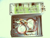
Checked by my experienced DIYer friend under an oscilloscope that power supply and phonoclone enclosures are immune from RFI. The suspect is the phono cable. Ferrite beads do not work. I�fll try to replace by a well shielded one but difficult to find in China. An interesting observation is that the gain at 20k Hz signal rolled off a little bit (very minor) and at 20 Hz signal gain declined and the curve distorted due to limitation of the opamp. My friend said it explains the soft sound at the lowest octave and loss of fidelity at dynamic passage of which. He further said it is speakers dependent and may not be detected in book shelf speaker systems. The way to improve it is to reduce the gain or experiment with different opamps. Any one has ideas about this observation? See attached my clone.
Shao sent me the photo, which I've scaled down and posted below. The build looks beyond reproach (I'm jealous), so I hope he can sort out the noise problem without too much trouble.
The frequency response is quite adjustable within practical limits by changing the value of the output capacitor (bass) and gain (treble). For all reasonable combination of cartridges, gains and load impedances, however, the standard parts will give a bandwidth of in excess of 10Hz to 30 kHz (-0.5dB).
-R
Attachments
Hello Richard !
Received your bords some weeks ago , looking good !
Unfortunatly I haven't had the time to play with it until now.
In fact starting up this work is to read myself up from total ignorance to the point where I can post some sensible questions.
What I still don't understand is how I calculate the gain in a 0 impedance topology, to decide resistor value.
The Vout / Vs = Rf / Rs formula does not make sense to me when it comes to low internal impedance Cartridges, in example 5 ohms, output 0.3mV.
( Not that I have one at the moment , but I want to understand this ! )
Best regards hk
- Home
- Source & Line
- Analogue Source
- The Phonoclone and VSPS PCB Help Desk