
Here my little contribution. I revised the PCB ver 1.6 and did the following modifications:
-Changed the gnd traces for C8-C11 directly to COM as mentionned in one of the last post. I added 2 wire jumpers for that, sorry...
-Added star gnd at COM
-Rounded all traces corners
-Even bigger C3 support
-Increased supply power traces width for reduce trace resistance.
-Added two 3 pins selectable jumpers so we can install two sets of R1-R2 to support two differents cartridges gain.
Here the image
Attachments
I'm working on a double-sided Phonoclone PCB which addresses the grounding issue. It will be available in time for the next batch order. I'm also toying with the idea of a LM317 version, using only two regulators per channel instead of the four, presently.
I've been busy lately on unrelated things, sorry this is taking so long...
Richard
I've been busy lately on unrelated things, sorry this is taking so long...
Richard

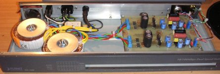
I just built a VSPS Ultra, completely double mono.
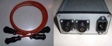
The box was a network hub, I will attach a frontplate. I removed everything except the mains connector and the switch and added a fuse an a mains filter. Of course, the fan is out of order.
For input, I decided to go with 5 pin DIN, as it easily allows some balanced groundfree wiring from the pickup to the preamp. I added a jumper, to go with or without input resistor.
Two 50VA 2x12VAC torroids, four fast rectifiers, LM7808/7908, Oscon caps. AD797.
The RIAA caps will be replaced by better caps later, maybe some silver mica or polystyrene.
Franz
Attachments
I get too low output level, out of the VSPS Ultra, driven with a Denon DL103 
Checking, measuring, calculating: everything seems to be O.K. The gain is about 54dB, the sinus and the RIAA is absolutely perfect.
But worlds away from "normal" sound level, the signal fed in the line-in of my poweramp.
I think, I cannot use it for my DL103 with this gainsetting.
Richard: how could I change it to 65 or 70 dB?
Franz
Hi Franz,
If you want more gain, use the phonoclone circuit.
On the VSPS Ultra page I specifically state "The circuit will produce 55 dB of midband gain from a DL-103 .." so you can't say you weren't warned.
Given you are using the AD797, however, you can probably wring a little more gain from the op-amp. To do this, however, you will have to replace all the RIAA values (R3, R4, R5, C1, C2) with R * X and C / X, where X is a constant in the range of 3-6.
The issue is the open loop gain of the op-amp. For the AD797 its 100dB at 1kHz. Ideally, I suggest keeping at least 40 dB of feedback which sets the closed loop gain maximum at 60 dB...
/R
Richard,
I have been trying to contact you via emails since end of August but with no reply from you.
I would like to get some circuit boards from you, would you please contact me at denniskmwong || at || ctimail || dot || com. I have missed the September's batch and I don't want to miss the coming batch again.
Thanks a lot!
On the VSPS Ultra page I specifically state "The circuit will produce 55 dB of midband gain from a DL-103 .." so you can't say you weren't warned.
Absolutely, you're right! It a logarithmic experience, as I was not aware, the output level is too low for my purposes.
Doesn't matter, I just adapted the board to a phonoclone design and will build this version into the ethernet hub box, as I want my personal consolidated solution.
Franz
Attachments
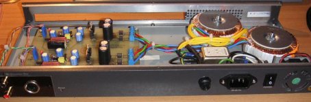
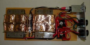
Here my own version of the power supply. It is fully dual mono. It uses 48VA, 8V-0-8V transformer producing more than 13Vdc at 40ma supply current (typ. PhonoCube power consumption). It is more than enough because I'll run the preamp using 9V regulators, not 12V. The transformers are shielded using 3M copper tape.
I'm using big rectifier bridges IR, 35MB100A.
The two outputs are on 4 pins AMP connectors. There is one pin for the cable shield that will be connected on the power supply frame (and AC supply main GND) only at one point and only at the supply end.
I'm using big rectifier bridges IR, 35MB100A.
The two outputs are on 4 pins AMP connectors. There is one pin for the cable shield that will be connected on the power supply frame (and AC supply main GND) only at one point and only at the supply end.
Attachments
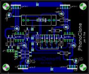
Phonoclone v1.7b
PC v1.7 is a double sided version, but still with four fixed regulators. I havent quite finished tidying it up, but the basic changes to the layout are all visible in the attached image.
- C8-11 grounding problem fixed, and increased to .2 (5mm) lead spacing typical of for 330uF or 470uF caps.
- um, its double sided...
- (scratch) that's about it, really. Oh, the width of the signal traces have been increased to 56 mils, and together with the plated through holes this should eliminate the delaminated solder pad problem that cropped up on the earlier boards after parts were repeatedly soldered and desoldered. (You know who you are... 😉
-rjm
Attachments
 Looks good. I particularly like the full ground plane. Count me in for a couple.
One suggestion however. If you're going to change it that much, how about changing to LM317 type regulators. This would make it easier to experiment with different voltages, and most people seem to prefer them to the 7800/7900 series.
Edit: Or LM320 series regulators. Not sure how these compare to the LM317s.

I'm working on the LM317 version. It will have only two regulators per channel, not four. I have had the single-sided layout in my head since way back - theres practically only one way to do it single-sided without jumpers - but putting it on half a Eurocard in a logical way is proving hard, unless I drop back to smaller resistors and offer less flexibility on the RIAA capacitor selection. Alternatively I could go with a double-sided layout, the problem is there are so many layout options to choose from I cant decide where to start.
To be single or double sided, that is the question....
-rjm
To be single or double sided, that is the question....
-rjm
- Home
- Source & Line
- Analogue Source
- The Phonoclone and VSPS PCB Help Desk