Yes. Actually it's a little higher than that (from a12Vac trafo you get around 17Vdc).Does the phonoclone use the same 12VDC+,Ov and 12VDC- that the VSPS uses?
After playing with the Phonoclone I have two comments. I settled on R2 = 1K8 for now.
1. The Phonoclone is as dead quiet as you could hope for. No hum, buzz, noise. Can't hear the difference between my CD input and Phonoclone from 10 cm. Perfect.
2. R1 = 0R doesn't work for me. Kills the stereo focus. I played Suzanna Vega's Luka album with 47R and with a bypass wire. With 47R here voice is nicely steady, with 0R her voice jumps from left to right of the middle.
Ralph
Ralph,
Thanks for posting the photos. I can see from them that there is no ground lug to attach the turntable ground to. It would normally be next to the RCA jacks. The connection scheme can be found here.
That's an interesting observation regarding R1. Can't explain why it should be so, but neither can I explain why the phonoclone should sound stange if R2 is increased above 3k.
/R
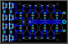
Sorry if this sounds stupid. I have read this thread from the first post to here. Read thru Richard's website. But I can't find out what the values are for the power supply caps, in the VSPS 1.7 design. These are C4 - C9.
Can anyone please post the values.
Thanks.
Can anyone please post the values.
Thanks.
I may not have spelt it out exactly before.
For the LM3x7 regulators, you want about 330-680 uF on the input (C4,C5), 100-220 uF on the output (C6,C7), and 10-100 uF at the adj pin, (C8,C9).
I would use 480 uF / 100 uF / 100 uF.
Richard
For the LM3x7 regulators, you want about 330-680 uF on the input (C4,C5), 100-220 uF on the output (C6,C7), and 10-100 uF at the adj pin, (C8,C9).
I would use 480 uF / 100 uF / 100 uF.
Richard
Hello.
This is may first post on this forum 🙂.
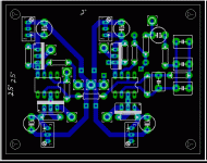
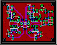
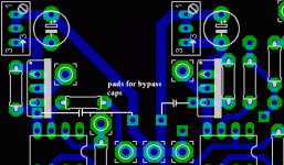
I'm going to made phonoclone pcb, and I've just made an eagle layout. And I got a question:
1.is it good or bad ?
2.should I change sth?
3.I wanted to place v-regs as close as possible of opamps - is it good idea or....not 🙂
Regards
Chris
This is may first post on this forum 🙂.
I'm going to made phonoclone pcb, and I've just made an eagle layout. And I got a question:
1.is it good or bad ?
2.should I change sth?
3.I wanted to place v-regs as close as possible of opamps - is it good idea or....not 🙂
Regards
Chris
Attachments
Looks OK to me. There are no capacitors on the input or the output of the regulators though...
/rjm
/rjm
I've got my phonoclone running for a week now and I am quite happy with it. Always looking for improvements, I was wondering what the consensus is about C8-10. I'm using 100uf in C10B/11B only. Has anyone tried using more capacitors? Does it effect the sound? I sometimes feel the overall sound is a little bit too harsh with voices but can't pinpoint it well enough.
Ralph
Ralph
Even after a week the components haven't fully settled in yet. The sound will mellow out further in the next 2-3 weeks.
The BE board has many possible options for the capacitors. I did not make any comparisons, but simply stuck 100 uF in each of C8b-11b and left it at that. I have 2x330uF in C4 and C5.
Also, its worth having a second look at the alignment of your cartridge. The phonoclone can reveal a poorly aligned cart much more dramatically than noisier, less resolving phono stages. That's how it was with me, anyway.
Richard
I had an interesting idea if anyone is interested. How about mini version of the VSPS or phonoclone using SMT parts? I don't have any PCB layout tools, otherwise I'd try to shink the PCB's myself. I could imagine that the PCB's would end up quite tiny.
It would indeed be small, but, and I'm just curious: have you ever soldered SMT parts onto a PCB? I can't do it. I quickly came to the conclusion that through-hole is for humans, SMT is for robots. Dont let me stop you though ... 🙂
rjm, its very easy to solder 1206 and bigger caps and resistors and also SOIC, QFN chips.
whitelabrat, try EAGLE layout software, there is free version also.
whitelabrat, try EAGLE layout software, there is free version also.
I'll have to check out the eagle tool. I've played with a viewer, which may be the same thing. May take a couple months for me to get anything going. Kids.
SMT isn't so bad. Just need a very thin soldering point on your iron, good lighting, a magnifying glass, and tweezers. It's certainly not quick either. There are some really tiny parts out there and those should be avoided, but some of the larger SMT bits are reasonable to work with. I've been assembling an AMP-4 with sloppy, but functional results. I'm certainly no robot.
Stay tuned.
SMT isn't so bad. Just need a very thin soldering point on your iron, good lighting, a magnifying glass, and tweezers. It's certainly not quick either. There are some really tiny parts out there and those should be avoided, but some of the larger SMT bits are reasonable to work with. I've been assembling an AMP-4 with sloppy, but functional results. I'm certainly no robot.

Stay tuned.
- Home
- Source & Line
- Analogue Source
- The Phonoclone and VSPS PCB Help Desk


