I happen to have a brand new unused 50VA transformer. Can I safely use this (2x15V) trafo for the project or does it really have to be 2x12V?
No, 2x15 is fine. The voltage going into the regulators will be 4 V - 4.5 V higher, but this is of no consequence. You can, if you wish, raise the output voltage of the regulator to compensate, up to a maximum of 15 V, but I think we've already established that the circuits sound better at lower voltages (10V) rather than at voltages close the the datasheet maximums.
It is possible to add a second regulator in series, but it is not necessary I doubt it would improve the sound.
Now back to Onvinyl's post.
I'm somehow reluctant to close the ... the actual box
On the other hand, it must be allowed that had you left the box closed you would still have a working cartridge, no? Unfortunately I dont have a solution for this. The sudden failure of one of the supply rails during use will bork your cartridge, and as far as I can see it is far easier to reduce the likelyhood of this failure mode (i.e. use a reliable power supply, and keep the lid shut!) than devise and install protection circuitry.
One idea that comes to mind is to add ~100 ohms in series with the cartrige, such that 0.6 V will not generate enough current to kill anything. Its not technically a phonoclone then, but it should be a pretty decent MC stage anyway.
/R
rjm said:
On the other hand, it must be allowed that had you left the box closed you would still have a working cartridge, no?
One idea that comes to mind is to add ~100 ohms in series with the
/R
Hi rjm, no offence meant! The psu didn't fail since then, and if it didn't start at all nothing would have happend 'cause I check it everey time I switch it on...
I tried the mod with the series res before, and it has an additional advantage: the gain isn't easily changed with different cart's source impedances. But the sound .... suffers. No surprise here.
The reason I asked is, that I can't think of a way to constantly measure for offset at the input without affecting the signal, perhaps someone else can?
I will take the second best route then and monitor the supply voltages after the regs. I will have to live with the risk that a faulty chip may develop too much offset und kill my cart (those can be expensive, we know that)
Of course, the risk is much lower if I don't place my circuits on a blank wire

Rüdiger
I don't think monitoring the supply voltages is second best if that is what you are protecting against - a supply voltage drop out. Failure of op amps or signal path components is another matter, but less likely to occur? I don't know, that depends on a lot, including assembly techniques.
This is how I plan to implement protection:
The signal disconnect at the cartridge has to be fast enough to limit any current surge. A small resistor and a switching transistor across the cartridge output would probably do it. Turned off, the shunt transistor should not affect the signal, but this must be verified as to leakage and capacitance. The power supplies would be filtered with a small R/large C filter. The sensing would be before the resistor and the sensing circuit would react well before the filter capacitor decays to a dangerous level. This would all have to be calculated a out, but at first glance it seems doable.
I went out of the room and came back to add to this. I would use a fast reed relay as a shunt instead. Although slower, it would shunt lower offset than a solid state device and would be less likely to degrade the signal. It could even be used to interrupt the signal in series. The time to close (or open) would have to be quicker than the time for the supply caps to decay to a dangerous level. The circuit should also shut down the supply.
Today I've ordered the Phonoclone boards and started on the part list. I'd like to check some items just to be sure. My cartridge is a Denon Dl-103, 0.38mV output.
1. What's the best R2 value for this cartridge? 1k5?
2. Should I load both C4 and C5? (I'm planning to use Cerafine 470uF/25V)
3. What's the opinion on C8-C11? Will 2 100uF caps per channel be enough (I'm planning to use Panasonic FC)?
4. What resistors are worth spending a Allan Brandy for? I'm planning R2, R3, R4, R5, R6. The others will be normal 1% metal films.
Thank you very much,
Ralph
Of course, the risk is much lower if I don't place my circuits on a blank wire
No offense taken of course, I was just trying to delicately point out that this is extremely unlikely in normal use, so an elaborate strategy to protect against it is difficult to justify even under "Murphy's Law".
The one action I do worry about is hot-swapping the Phonoclone into a power supply that is already powered up. I do it all the time and can report no problems, but if you just get it wrong and one contact is made substatially after the other two, you could perhaps be unlucky enough to strike out your cart... if it worries you, then always connect the phonoclone to the cold power supply before connecting the mains.
To quickly answer Ralph's post:
1. It depends on your system.
2. C5 and C4 both have up to two capacitors each. Again its up to you to try both configurations.
3. Two or perhaps four per channel.
4. R1 - R4.
Quick question..
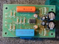
What is the value of R8, 9, 10, 11 on the VSPS?
I just completed all the other parts with exception of the 337 and 317 regs and associated biasing resistors.
I don't see the R8-11 resistors value on the webpage and I did a search on this thread with no luck.
I can use any transformer suggested but have 12, 15 and 21 volt handy.
Attachments
Hi Troy
It depends, on what voltage you want to drive the VSPS.
When you look at the datasheet from the LM317 you find the (simplified) formula:
Vout = 1.25 * (1 + R10/R8)
Example: R8 = 120 Ohm
R10 = 1,2k
will result in 13.75VDC
As you could think, use 1% resistors or better.
About your trannies: the input DC-voltage of the LM317 should be (tumb rule) at least 4V higher than the output, giving the LM317 the "freedom" to regulate the voltage.
Your 12V trannie should work for 12VDC, the 21V trannie will result in hot regulators.
Kind regards
Franz
Not that I can't do math, but I was looking to see what the "tried and not fried" values were..
I will go with a 12vac tranny and 12VDC rails.
I will go with a 12vac tranny and 12VDC rails.
various
Hi dears,
I am new in this 3D. To be honest I tried to trace the whole 3D... but is really impossible to go through all this material.
First of all thanks to Richard all the guy involved. I got here because I listened to the true PhonoCube and I was really impressed. After years and years of listening highend systems, and as a Countepoint SA-5000 owner, I thought nothing more was possible. An extended listening test showed me the extreme quality of the sound of the phonocube... but it is too expensive given the few components used.
So I went back to Arthur Salvatori's page (one of the biggest guru in High end audio) and I discovered he has a good score on the phonocube. Searching the web, then, I arrived here.
First of all I suggest to go the the Salvatori's page where there is also some techincal description of the PhonoCube.
http://www.high-endaudio.com/RC-PhonoStages.html#ClB
I don't have the money for a PhonoCube now, so for the moment I want build a PhonoClone for my second studio system... but if it will be close to the PhonoCube... I will sell the SA5000 and put the PhonoClone in my primary system!
I have some questions and I hope somebody in the forum can help me:
1. The true PhonoCube has 24V psu, why the PhonoClone here is run at 12v?
2. Is that possible to remove the LM337 on the -V and replacing the LM317 with a single discrete regulator? Does somebody tried out some discrete regulator (eg. Jung SuperRegs)?
3. I am a bit confused about the sonic differences between the PhonoClone and VSPS ultra specifically arranged for the Denon DL103. I am a Denon DL103 user, so which board is suggested and why? What is the differences between a DL103 with a PhonoClone and a VSPS ultra?
4. I do not use digital sources, is that possible to add a volume pot at the output so that I will not use a line preamp?
Thanks for your attention,
Cheers,
John Cukkurullo
I made the vsps ultra w/ dl103.However I was not satisfied with the sound.Sounded slightly shut in and boomy compared to unmodified circa 1980 Naim 323 phonoboards.
Used opa 627.Opa 637 oscillated despite the AW mod.I was disappointed because another simple phonostage I had made some time ago (for a friend)with opa 627 for mm cartridge from slone´s book sounded really good.
Used opa 627.Opa 637 oscillated despite the AW mod.I was disappointed because another simple phonostage I had made some time ago (for a friend)with opa 627 for mm cartridge from slone´s book sounded really good.
The regular vsps sounds quite nice combined with a little more TLC in the PSU department, some decoupling caps and an opa2228.
I'm sure there is better out there, but even with a cheap table and cartridge I think it still blows my playstation out of the water as a source.
I'm sure there is better out there, but even with a cheap table and cartridge I think it still blows my playstation out of the water as a source.
1. The true PhonoCube has 24V psu, why the PhonoClone here is run at 12v?
The Power Humpty output is about +/-24 V, but the voltage to the opamps is regulated internally in the Phonocube down to 15 V or less.
2. Is that possible to remove the LM337 on the -V and replacing the LM317 with a single discrete regulator? Does somebody tried out some discrete regulator (eg. Jung SuperRegs)?
Only if you implement a virtual ground. // Ask Onvinyl about the plusses and minusses of the Superegs.
3. I am a bit confused about the sonic differences between the PhonoClone and VSPS ultra specifically arranged for the Denon DL103. I am a Denon DL103 user, so which board is suggested and why? What is the differences between a DL103 with a PhonoClone and a VSPS ultra?
The VSPS Ultra was a little side project intended as an modification path available for existing VSPS owners to upgrade to an MC cartridge. If you are building from scratch I suggest going with the Phonoclone since it is properly field tested and far more flexible.
4. I do not use digital sources, is that possible to add a volume pot at the output so that I will not use a line preamp?
Of course, though its better to put the volume control at the amp end of the interconnect cable, c.f. the Gainclone.
I think it still blows my playstation out of the water as a source.
Me >> Sony 😀
.....
Protos, its not at all certain that either the 627 or the 637 are a good choice for this circuit. Please give the OP27 a shot - and give everything a couple of weeks break in time - before writing it off as inferior to the Naim. Heck, for all I know the 323 might be the better sounding circuit ... but I dont think you're giving the VSPS Ultra a fair shake.
Oh right, Happy New Year everyone! Unfortunately I dont think I'll have time to do kits or even board orders this year either, so hopefully having the board files available online is working out for most people.
/R
Hi
I'm looking to build my first MM phono stage and came across the phonoclone. However, the amp I'm looking to put it in only has single supply rails - does anyone have a revised schematic for using it with single supply?
Thanks in advance
James
I'm looking to build my first MM phono stage and came across the phonoclone. However, the amp I'm looking to put it in only has single supply rails - does anyone have a revised schematic for using it with single supply?
Thanks in advance
James
You can't power the circuit from a shared single supply. Ok, technically its possible, but its a horrible idea involving input blocking caps and voltage dividers. Please build the phono stage as an external box with its own power supply. -R
which version?
Hi Dear,
is it recommended to use the OP27 in both stages of the Phonoclone? There are several version of the OP27, I was suggested to use the OP27G, but I see that after the G there is onother letter.... which one to buy?
Thanks amd happy new year!
Cukkurullo
Hi Dear,
is it recommended to use the OP27 in both stages of the Phonoclone? There are several version of the OP27, I was suggested to use the OP27G, but I see that after the G there is onother letter.... which one to buy?
Thanks amd happy new year!
Cukkurullo
The additional letter codes signify different packaging, grades, and temperature ratings. The OP27 is also made by at least two different companies. (AD and Burr Brown-TI)
You want the OP27GP. G:eneral use/ P:lastic package
You want the OP27GP. G:eneral use/ P:lastic package
I've built recently VSPS using modified Veteran boards with all critical components connected p2p underneathe the chip. I also omitted some output resistors. The chip is OPA627, all caps BG, resistors are Caddocks, regulators LM2990/2937. It worked pretty well by itself, but it's really good with S&B TX 103 in step up (with Shelter 901).
The setup in a picture is better than CEC TL0 with modified BiDAT.
The setup in a picture is better than CEC TL0 with modified BiDAT.
Attachments
- Home
- Source & Line
- Analogue Source
- The Phonoclone and VSPS PCB Help Desk