The 2.2 uF caps will be fine for C3.
C8, C9 are the capacitors that bypass the ADJ terminal of the regulator. They should be 10 uF or more, but the exact value is not critical. Use whatever you have that fits.
/R
C8, C9 are the capacitors that bypass the ADJ terminal of the regulator. They should be 10 uF or more, but the exact value is not critical. Use whatever you have that fits.
/R
hey thanks for that.
almost completed my ghetto vsps for testing 🙂
the power socket/fuse & switch I ripped out of an old 2/4gb tape drive 🙂
all wired up, all I needed was to hook the active/neutral up to the trannies...
Expensive casing supplied by my shed ;-)
plastic mounts for vsps pcb with some old motherboard mounts that I pushed into some holes I made with a drill.
Only thing left is to wak in the rectifiers, and watch the smoke... hopefully not. 🙂
An externally hosted image should be here but it was not working when we last tested it.
An externally hosted image should be here but it was not working when we last tested it.
Random thoughts:
You dont need heatsinks on the voltage regulators.
Remove the opamps from the sockets before you power everything up the first time. Assuming a smokeless excecution, proceed to measure the voltage at the socket power pins to make sure they are correct before unplugging the whole thing, re-socketing the opamps, and heading out for the listening test.
The caps you are using for C1 and C2 are pretty icky, other than that despite what it looks like Id say its a solid job well done. I especially like the chunky dual mono supply.
In general people will have to consider for themselves whether - neglecting the educational value - making your own PCBs like this, drilling all the holes, etc, is really worth the effort vs. doing it all point-to-point on perf-board or paying $30-35 and getting Olimex to deliver two sets all pretty and finished. I've never made my own PCBs, but I can speak for the other two options as being both cheap and easy alternatives.
awesome, thanks for the input.
will remove heatsinks & opamps before power on.
If it works Ill proceed to test with opamps, then probably replace c1/c2.
I had a hughe time trying to work out exactly WHAT caps to put in c1/c2 :-/ as I have bucket loads of cap's, but not sure of their values...
so I am looking for 1nf = 102
and 330pf = 331
correct?
In the end I just got whatever the shop had in those values.
I can never seem to work out what a Polypro film/metal cap is, and what they look like, which is what the build says to out in, and looking at the photo's of other vsps's, just confuses me more, as there are some with wires in each end and are clear, others have used the tube shaped caps.
kind regards, confused cap-man 🙂
I've had a look and I have these choices for c1/c2:
I recon, either the extendid foils, or the tubular foil's...
help me make a choice please.
Or, if there is something else I can get thats better around the same cost, in australia...
cheers, stevodude.
An externally hosted image should be here but it was not working when we last tested it.
I recon, either the extendid foils, or the tubular foil's...
help me make a choice please.
Or, if there is something else I can get thats better around the same cost, in australia...
cheers, stevodude.
For C1 I used 484-2000 330pF wima FKP2 polypro and for C2 I used 1.0nF 484-2038 also FKP2 polypro. Don't mind the green in the pics on the RS site, when they come they will be red with yellow resin fill. Both available at small money.
If you want, and I'm not sure how to do this, but I have my parts list with RS saved, I bought nearly everything for my VSPS from them, if its any use to you, let me know and I can send it on to you.
I couldn't get the Blackgate non polar for C3 from them and its well worth while hunting some of them down, its black gate N-series 4.7uF caps you'll need. (Good advice there Richard on those caps BTW)
This phono stage is well worth the build!
Fran
I'd go with silver mica here. Good polypro film+foil is about the only alternative, Wima FKP or "audio" brands, but they are expensive or hard to track down in the small values and Im not convinced they sound better than mica anyway.
So given the choices above the silver mica caps get the nod from me. The polystyrene are pretty decent, the no-brand generic metallized polypro a distant third.
I know, its just a capacitor, nothing to lose sleep over. Still without fussing excessively over it just a small amount of care spent making sure the components fall within a certain level does make a difference.
/R
sorry for the dumb questions on here, just just trying to make the selection simple, but efective 🙂 . Maybe this'll help someone else with selecting caps in asutralia 🙂
OK, I have re-done capacitor selection, on all capacitors in the values I'm after, plus in the product type selection.
this will be my last selection, I'll order a bunch after someone responds, cheers and thanks for all your help so far. Learning all the time 🙂
OK, I have re-done capacitor selection, on all capacitors in the values I'm after, plus in the product type selection.
this will be my last selection, I'll order a bunch after someone responds, cheers and thanks for all your help so far. Learning all the time 🙂
An externally hosted image should be here but it was not working when we last tested it.
That makes it easy doesnt it?
If you dont mind spending $20 on caps : silver mica.
Otherwise go with the Wimas, which will give 70% of the performance at 10% of the price. Unless shipping and minimum order charges come into it, if you can get the Wimas in single unit quantities this seems like the better deal.
If you dont mind spending $20 on caps : silver mica.
Otherwise go with the Wimas, which will give 70% of the performance at 10% of the price. Unless shipping and minimum order charges come into it, if you can get the Wimas in single unit quantities this seems like the better deal.
money isn't really the option, just best quality for reasonable cost, so I'll go the silver mica's, cheers.
Oh, I have also got some 4.7uF n-series BG's comming 🙂 for c3.
cheers, will see how it compares to existing phono inputs I have.
This is mainly for digitally recording some vinyl to wav/flac.
Oh, I have also got some 4.7uF n-series BG's comming 🙂 for c3.
cheers, will see how it compares to existing phono inputs I have.
This is mainly for digitally recording some vinyl to wav/flac.
woot, worked first go!.... I'm simply amazed 🙂
little bit of buzz when I put my fingers near the TT interconnects - I think they don't have a very good earth surrounding the signal wire - plastic... will replace with gold connects.
Apart from that, great sound, plenty of bass and voice, little bit of background hiss, but minimal considering it's an old record, but clean sound...
awaiting some caps for a bit of tweaking, Oh and an LED to tell me it has power

Just amazed it worked the first time I kicked it in the guts ( powered on after power-pin test 24.5v spot on both IC sockets ) ... hahaha 😀 😀 😀
😀 😀 😀
Mwwwahahahaha, damn... just gotta spend more money, comon wifey, get out and work more so I can spend it 😉 😀
😉 😀
little bit of buzz when I put my fingers near the TT interconnects - I think they don't have a very good earth surrounding the signal wire - plastic... will replace with gold connects.
Apart from that, great sound, plenty of bass and voice, little bit of background hiss, but minimal considering it's an old record, but clean sound...
An externally hosted image should be here but it was not working when we last tested it.
An externally hosted image should be here but it was not working when we last tested it.
awaiting some caps for a bit of tweaking, Oh and an LED to tell me it has power
Just amazed it worked the first time I kicked it in the guts ( powered on after power-pin test 24.5v spot on both IC sockets ) ... hahaha
😀 😀 😀Mwwwahahahaha, damn... just gotta spend more money, comon wifey, get out and work more so I can spend it
😉 😀The returns (ground) of the input and output signals are connected internally on the PCB. Once away from the board they should be considered separate and not allowed to short together through the case. It looks like you've shorted all the returns together at the metal bracket holding the cables, though I cant see too clearly. Ideally you'd want to use RCA jacks with an insulating plastic washer for the output signal so they are isolated. With a dual mono supply you can connect both input commons to the case. (With a single transformer you keep the input signal isolated from the case and connect the case to the power supply common.)
so to re-iterate what your saying is:
1. If you have 2 trannies, one for each channel, you should isolate the output channels.
2. If you have a single trannie, you should isolate the input channels.
So I isolate the output rca's...
regards, stevo.
1. If you have 2 trannies, one for each channel, you should isolate the output channels.
2. If you have a single trannie, you should isolate the input channels.
So I isolate the output rca's...
regards, stevo.
on the subject of common ground....
Hi Richard,
this raises a Q from me,
I have my VSPS in a 2 box set up. The PSU is in one box, dual mono, chassis of that box earthed to normal electrical supply. Live and neutral feed the two toroids. Power output leaves each rectifier board in a 3 core cable, one for each channel, carrying ground/+DC/-DC terminated in a XLR plug/jack setup into box 2.
Box 2 contains the vsps and in this the inputs and outputs share a common ground, but this ground is not connected to the earth in the PSU box.
So the inputs and outputs have common ground, but this is not shared with the power supply ground.
Is this config OK, or should I be fitting the insulated RCA jacks?
Thanks,
Fran
1. If you have 2 trannies, one for each channel, you should isolate the output channels.
2. If you have a single trannie, you should isolate the input channels.
Nooo.....

If you have two transformers, the input ground of each channel connects to the case (non insulated jack). The output ground does not connect to the case (insulated jack).
If you have a single transformer the input ground of each channel is insulated from the case (insulated jack). The output ground also does not connect to the case (insulated jack). The case is connected instead at the power supply common where it splits in two to feed each channel. As shown in the VSPS building guide on my web page here.
The AC earth connects to the power supply case. The power supply case does not connect to the power supply common. Unless the power supply and the amp are in the same case.
God that gets awfully complicated when you try to explain it in words.
Fran (and Steve too, same situation essentially): The output RCAs should have insulated spacers. The input RCAs can be left as is.
For everyone, please remember that the input common, output common, and power supply common are all connected to each other inside the VSPS (and Phonoclone) PCB. In the layout of the traces, I specifically worked out the order in which all the returns connect. If you start connecting input and output commons together randomly on your own, through a shared connection to the case for example, its going to create ground loops because the connection order gets all messed up.
OK sounds much better now 🙂 if it could...
Anyway thanks for your help, but another question, but probably would need to be in a seperate thread, as it is now noticable with the vsps & recording the vynal, is I can hear when it's flat up load and in song breaks I can hear a wooosh wooosh wooosh sound... this a problem with the turntable or needle - I have a nice new needle turning up next week.
Anyway thanks for your help, but another question, but probably would need to be in a seperate thread, as it is now noticable with the vsps & recording the vynal, is I can hear when it's flat up load and in song breaks I can hear a wooosh wooosh wooosh sound... this a problem with the turntable or needle - I have a nice new needle turning up next week.
OK, I'll rearrange mine and report back, although I have no hum or anything like that - my VSPS is pretty quiet. But I will fit the insulated outputs.
thanks
Fran
thanks
Fran
The VSPS is non-inverting, so output coupling back to the input produces positive feedback... one does have to be careful, though I'd be surprised if you hear any difference in this instance as the transgression is very minor.
OK,
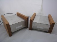
finally got to do a few pics of my completed VSPS. BTW, I changed the output jacks to insulated and it does actually make a small but noticeable difference, things like the decay of notes, ringing in drum beats etc.
As I said above, the format is a 2 box affair with transformers and rectifiaction in 1 box and then the 2 VSPS boards in the other. Boxes are simple alu boxes from maplin, side cheeks are oak. I added the labels just to set it off!
Attachments
- Home
- Source & Line
- Analogue Source
- The Phonoclone and VSPS PCB Help Desk