I'm not surprised they cause problem.
I know I go against common belief here, but I doubt there's anything to gain from using the OPA637. The OPA37 is already excessive. You want more signal swing, not higher bandwidth.
If you want to play around with it, try replacing the output caps with transformers, 600:600. That should give you signal swing--"transparency," "openness" or whatever subjective words you look for.
Hi,
I've just bought an Audio Technica OC5 and have decided to have a go at constructing a Phonoclone.
A couple for questions for those who know and have time:
1. I'd like to use a battery power supply. I have 2 12V LA batteries already - will these sufficient on their own and is there a 'prescribed' method to implement a battery supply for the phonoclone??
2. What would be a good alternative to Rikens for R1 & R2? They are hard to get in the UK.
Thanks 🙂
Hi Ropie,
what coil-impedance the OC5 does have? As a rule of thumb, the lower the better suited for a phonoclone (a DL103 at aprx. 40 R is fine, however)
My experiences with lead batteries weren't that good. I use a super regulator, which gives me a lot more life in the music and a nailed-on placement of instruments. I would try local regulators, if the PC-board provides space for it.
I use Dale resistors allover, but honestly, I wouldn't bet I'd hear it if someone would exchange them overnight...
Rüdiger
Hi Rudiger,
 What is a super regulator?
12R - should be fine...Onvinyl said:what coil-impedance the OC5 does have?
The batteries aren't essential but I thought it would be simpler than building a new PSU and would avoid RFI problems. I'm not using any of RJM's boards and would find it tricky to make my own PSU without following a schematicMy experiences with lead batteries weren't that good. I use a super regulator, which gives me a lot more life in the music and a nailed-on placement of instruments. I would try local regulators, if the PC-board provides space for it.
What is a super regulator?😉 ThanksI use Dale resistors allover, but honestly, I wouldn't bet I'd hear it if someone would exchange them overnight...
Ropie said:What is a super regulator?[/B]
have a look
It is a project on its own, but worthwhile.
As a start, I would use local regs close to the chips with e.g. LM317/LM337 as shown in the datasheets. there are a few threads around here to improve performance of that regs. As far as I remember, rjm documented his PSU as well.
I'm not saying batteries don't work, but in this case it's not worth the hassle imho,
Rüdiger
Thanks, as you say it is a whole new project!
I think I'd still like to try the battery implementation as it has worked well for me in the past and I have the batteries to hand.
Looking through this thread I see Franz G had good results with a battery PSU - any more info on how you built this, Franz?
I think I'd still like to try the battery implementation as it has worked well for me in the past and I have the batteries to hand.
Looking through this thread I see Franz G had good results with a battery PSU - any more info on how you built this, Franz?
Ropie said:
1. I'd like to use a battery power supply. I have 2 12V LA batteries already - will these sufficient on their own and is there a 'prescribed' method to implement a battery supply for the phonoclone??
hi Ropie
2 x 12v SLA is sufficient for the psu.
i am still using SLA for my VSPS. so far so good. runs for a long time (did not experiment on how long they last) before i need to recharge the SLAs.
cheers
garbage
I had much better results, with double mono psu: two trannies followed by separate rectification and regulation.
The simplest battery psu: fuses (important to avoid incident) and electrolytic caps.
I recommend to use a resistor as additional load, as the idle voltage from a battery could be higher than with the few mA load from the VSPS.
Kind regards
Franz
The simplest battery psu: fuses (important to avoid incident) and electrolytic caps.
I recommend to use a resistor as additional load, as the idle voltage from a battery could be higher than with the few mA load from the VSPS.
Kind regards
Franz
I've touched on the subject before, but Franz's comments about the super reg. reminds me again of the importance of the regulator to the VSPS and phonoclone circuits. I felt the LM317 was audibly better than the LM7812: smoother and more tightly controlled on complex passages. Measurements, however, show how they both suffer from the same design limitation: basically, they are largely ineffective at removing power line noise much above 1 kHz.
Its not a flaw, National engineers tune these chips for iron clad (and idiot proof) stability rather than thoroughbred performance.
Its also not all that serious. The opamp PSRR mops up most of the leftover, so, as those of you who have built the circuits know, the output noise floor is pretty much the opamp voltage noise. Using batteries doesnt get you a lower noise floor.
Still, small amounts of higher order ripple do get through, as does assorted high frequency grunge, and a couple of millivolts RMS generated by the regulator itself! It would be nice to have a low noise regulator with an effective bandwidth out to 20 kHz at least.
The superreg fits the bill, but its complex and sometimes I wonder if its a little too tweaked out for its own good.
I found this today and I though it was kinda neat. I like the idea of using a follower rather than a regulator. No need for a voltage reference! Its not going to match the performance of the superreg but should be a big step up from the LM317... with some tweaking ... without very much additional complexity.
/R
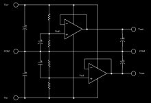
The attached circuit is a voltage follower to power a phonoclone or VSPS. It is just a design idea for now. Its simple and cheap enough that I figure its worth a "try and see" test.
The concept is to use an opamp instead of a regulator to provide a clean DC signal for the phono preamp. An amplifier to power an amplifier. Since the current draw is so low a pass transistor isnt strictly needed, especially if the opamp is a of the power variety, like an LM3875. For the VSPS or phonoclone, even the current output from an OP27 would be sufficient.
The choice of opamp is limited to something that works well as a buffer, unity gain configuration. High PSRR, low noise, and low input currents are also desirable.
The reference voltages Vref+ and Vref- are generated passively as a fraction (I would aim for 3-4 V below the input) of the input DC signal. A zener or other fixed voltage reference could be added to make the circuit a regulator rather than a follower, but I stress again there is no performance advantage in doing so.
This circuit would replace the LM317/LM337 on board. It is complete only in concept, stability issues and protection may require additional components. Use at your own risk.
/R
Attachments
Is it possible to use a high output MC like my Dynavector that have 330 ohm impedance with phonoclone or VSPS ultra?
STaffan
STaffan
It is ... possible. The high impedance automatically lowers the circuit gain. Thats ok, but the increased bandwidth on the first stage may lead to problems. The usual caveat that the impedance of the cartridge must stay constant over audio frequencies still applies.
/R
/R
Stupid Q here maybe,
what is the difference between the VSPS and VSPS ultra?
(couldn't access your site today RJM - might just be my work firewall)
Fran
what is the difference between the VSPS and VSPS ultra?
(couldn't access your site today RJM - might just be my work firewall)
Fran
VSPS - noninverting, input impedance fixed by R1, gain fixed by R2. Works with all manner of high output cartidges, MM MI or MC.
VSPS ultra - inverting, input impedance zero, gain set by cartridge impedance. Basically suited for the DL103 and thats about it.
Phonoclone - Two stage. Input impedance zero, gain set by cartridge impedance and R2. Works with most low output cartridges.
I have never got any mail from people saying that the phonoclone does not work with such-and-such a cartridge, even though a while back some people were planning on using cartridges that I thought would be problematic.
/R
PS RJM Audio is sometimes down due to my bandwidth limits at Geocities. I know, I should get a real host or pay Yahoo real money. However it works 99% of the time as it is. If its down all you have to do is wait an hour, usually.
Thanks RJM,
was trying to figure it out from memory!
Site is back and accessible again, could well ahve been the connection here this end.
BTW, loving the VSPS but still waiting to recieve some blackgates for C3 that I ordered before I finsh the cosmetics.
Fran
was trying to figure it out from memory!
Site is back and accessible again, could well ahve been the connection here this end.
BTW, loving the VSPS but still waiting to recieve some blackgates for C3 that I ordered before I finsh the cosmetics.
Fran
this is probably a stupid question, but how come your board looks like this:
and eagle pcb layout looks like this:
The gound plane look different & there seems to be another layour/lighter blue overlayed which intersects the other tracks.
If I remove all layers apart from 'Bottom' & 'pads' the overlayed light blue is still in the way of thr tracks.
Reason Is I want to change the layout a little bit to suite alternative components that I have lying around, and want to play around with laser pcb etching for fun.
Please help, stevo.
An externally hosted image should be here but it was not working when we last tested it.
and eagle pcb layout looks like this:
An externally hosted image should be here but it was not working when we last tested it.
The gound plane look different & there seems to be another layour/lighter blue overlayed which intersects the other tracks.
If I remove all layers apart from 'Bottom' & 'pads' the overlayed light blue is still in the way of thr tracks.
Reason Is I want to change the layout a little bit to suite alternative components that I have lying around, and want to play around with laser pcb etching for fun.
Please help, stevo.
woot, finally got the pcb's etched @ home using the diy toner transfer method.
Took me till the third pcb to get it right 🙂, first 1 toner came off, second one worked ok, but one in/out pin came off - using clothes iron, 3rd one worked perfectly.
Printed onto a standard Glossy magazine page with an hp2100 LJ & 600dpi (max of this printer), and then feed through a laminator (GBE creative ) total of 10 times fed through alternating sides ( silk screening at same time), then soaked for 10 mins & removed paper.
adjitated in ammonium persolphate for 8 minutes & a clear spray coat.
ready for population. 🙂
copper side ( missed one in/out pin) - this was my second attempt, but will use it for one of the channels
silk screen side
Took me till the third pcb to get it right 🙂, first 1 toner came off, second one worked ok, but one in/out pin came off - using clothes iron, 3rd one worked perfectly.
Printed onto a standard Glossy magazine page with an hp2100 LJ & 600dpi (max of this printer), and then feed through a laminator (GBE creative ) total of 10 times fed through alternating sides ( silk screening at same time), then soaked for 10 mins & removed paper.
adjitated in ammonium persolphate for 8 minutes & a clear spray coat.
ready for population. 🙂
copper side ( missed one in/out pin) - this was my second attempt, but will use it for one of the channels
An externally hosted image should be here but it was not working when we last tested it.
silk screen side
An externally hosted image should be here but it was not working when we last tested it.
OK, starting to populate pcb,
my only issue's are 1,2,3
1. I have some big square orange 2.2uF 250v mkp's for c3, these be ok?(same hole size as pcb)
i am a bit confused about c8,c9 - the construction guide only says
"ADJ bypass bypass capacitors C8, C9 (100 µ:F/25V) "
2. each vsps channel will have it's own 20va 12-0-12 toroid ( all I have, as I got them cheap) - so do I need adjustable c8/c9 caps? or just throw in some 100u/25v caps...
3 if i'm going to use static caps not vaeriable, would it be better with:
3.a. 330uf/25v
3.b. or 470uf 16v
3. - I have plenty of the above.
- Home
- Source & Line
- Analogue Source
- The Phonoclone and VSPS PCB Help Desk