This transformer is nominally 6VA, which is way below the 25-50VA recommended for the VSPS. Yet at 250mA per rail, it sure seems like plenty of headroom for what I assume is a pretty low current amp (although my frame of reference is tube designs, which run at lower current but higher voltage). So first, what is the current in the VSPS (stereo)? And assuming it's below, say 50mA (1/5th of this PS transformer), can you talk, Richard, about why the high VA recommendation? It seems like at some point too large a power transformer could be problematic (inducing noise, huge startup currents, etc.)? Note my VSPS, out on loan to a young new vinyl fan, has a much larger power transformer though I don't recall it's exact rating.
I decided 250mA per rail is enough for myself based on the fact that the recommended fuse on the live input is 250mA total, so the transformer is going to be using at most half its rated power without blowing the fuse
25 VA is a reasonable size. It's not much more expensive than the 6 VA model, not - for most builds - significantly larger, and is much better value in terms of "power per dollar".
Larger transformers have better line regulation and lower output impedance.
In a AD/DC power supply, the transformer only operates for short spikes every cycle, to rapidly charge the capacitors. The rest of the cycle, the circuit is powered by the filter capacitors. This is built into the design of power transformers, but you do have to at least recognize that the transformer is working a little harder (for short periods) than you might imagine, and how the transformer handles these rapid start-stop of diode conduction will influence the sound quality (being deliberately vague here, to avoid getting in to arguments about what and what does not).
In short, for most people there is no reason not to use 25-50VA. It is technically an over-spec, however.
(being deliberately vague here, to avoid getting in to arguments about what and what does not).
LOL! No problem, and thanks for the reminders about transformers.
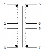
Well, I finished my power supply box today. Went a little awry and took much longer than it should have due to the fact that the way they do the pinning/datasheet/schematic for this transformer is a bit dumb and therefore I made a dumb error in the PCB design...
The schematic in the datasheet has the pins in order 1,2,3,4 and 5,6,7,8.... On the device, the pins are all in order, *except* pins 3 and 4 are in reverse order. ��*♀️��*♀️��*♀️
I mean, this makes sense, but why would you not just mark this on the schematic rather than actually reverse order the numbering of the pins on the device itself. GAH.
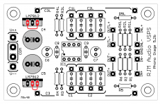
Anyhow, I was able to remedy the situation by cutting a chunk out of the traces that bridge the footprints in position 1/3 and 2/4 and then running jumpers to bridge the *actual* pins 1/3 and 2/4 (in positions 1/4 and 2/3) instead. Now it's running great 🙂
My offer to send out an extra board is no longer valid, though, as I don't want to send out a board in this state to anyone. I've corrected the design and added better markings if anyone is interested in making one themselves still, though. Should be around $10-25 depending on shipping for 5 of them from JLCPCB. See here for the full design and Releases page for zipped gerbers ready to submit to your choice of manufacturer GitHub - termhn/vsps-power: Power supply for VSPS (Very Simple Phono Stage) by RJM Audio


The schematic in the datasheet has the pins in order 1,2,3,4 and 5,6,7,8.... On the device, the pins are all in order, *except* pins 3 and 4 are in reverse order. ��*♀️��*♀️��*♀️
I mean, this makes sense, but why would you not just mark this on the schematic rather than actually reverse order the numbering of the pins on the device itself. GAH.
Anyhow, I was able to remedy the situation by cutting a chunk out of the traces that bridge the footprints in position 1/3 and 2/4 and then running jumpers to bridge the *actual* pins 1/3 and 2/4 (in positions 1/4 and 2/3) instead. Now it's running great 🙂
My offer to send out an extra board is no longer valid, though, as I don't want to send out a board in this state to anyone. I've corrected the design and added better markings if anyone is interested in making one themselves still, though. Should be around $10-25 depending on shipping for 5 of them from JLCPCB. See here for the full design and Releases page for zipped gerbers ready to submit to your choice of manufacturer GitHub - termhn/vsps-power: Power supply for VSPS (Very Simple Phono Stage) by RJM Audio
General update note:
From April 1 2021, Japan Post has increased the rates for small packet air mail shipping.
By a lot. Most bizarrely, they've changed the rate categories from 1. Asia 2. N. America and Europe and 3. Everywhere else to make a fourth category for the USA only, which is the most expensive all all. Yes, for some reason it now costs more for me to send 100g to New York than it does to somewhere in Mozambique.
I'm not kidding.
It used to cost me 150-240 yen to ship boards, and about 330-500 yen for kits. From now on it's going to be 480-750 for boards, and 600-880 yen for kits.
Counterbalancing this is the fact that I haven't updated he boards recently so the tooling costs have been largely amortized by now.
I'm not going to change the price of the Sapphire or Emerald kits, at $150, and I'll keep the price of the Emerald and Sapphire boards at $25. VSPS, Switchboard, and DBRB boards will increase by $5, as will for VSPS, Switchboard, and DBRB kits.
I will, however, formalize a discount rule that if you buy multiple items to ship together, each items after the first will have the price reduced by $5.
Changes effective immediately.
Richard Murdey
RJM Audio
7-8-6-5-3-4-2-1
Because of course it is! 😀
Hahah, yes of course, why did I not expect that? 😉
I mean, it does ultimately make sense because now you can just short out the middle two pins for parallel operation but ugh, the least intuitive way you could mark that change IMO, LOL
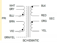
It is really odd though that your Triad transformer doesn't follow the same convention as the Triad VPM I've used before.
Normally the windings are drawn with the phase indicator (black dot) pointing in the same direction, not opposite to each other. Must be reflecting some details of the construction not obvious to the user. Funnily enough if the diagram is changed to the conventional layout the terminal numbers end up in order.
Normally the windings are drawn with the phase indicator (black dot) pointing in the same direction, not opposite to each other. Must be reflecting some details of the construction not obvious to the user. Funnily enough if the diagram is changed to the conventional layout the terminal numbers end up in order.
Attachments
Last edited:
Almost there! CADed up front and back plates for the main unit as well as an adapter plate for the PCB to sit in the groove mount (PCB just barely too small to fit on its own). Will finish up the wiring tomorrow! CAD is available here (Fusion 360 files and ready to print STLs) if anyone's interested to use or modify for their own build: GitHub - termhn/vsps: Casing & power supply design for VSPS (Very Simple Phono Stage) by RJM Audio


6DJ8 Phono preamp
All,
I hope this is an OK place to ask about the 6DJ8 tube phono stage from the RJM Audio website: RJM Audio - Tube passive phono preamplifier
I'm thinking of building this amp. I have a VSPS that I did on stripboard that I like a lot, also the "Wyn Palmer" phono preamp, which I like a bit more than the VSPS. But I'd like to build a tube preamp, and I'd also like to build it point-to-point. This one is appealing because it seems very simple.
In thinking through the circuit, I've got a few questions:
That's all I can think of right now. Thanks in advance for any guidance and help.
Dan
All,
I hope this is an OK place to ask about the 6DJ8 tube phono stage from the RJM Audio website: RJM Audio - Tube passive phono preamplifier
I'm thinking of building this amp. I have a VSPS that I did on stripboard that I like a lot, also the "Wyn Palmer" phono preamp, which I like a bit more than the VSPS. But I'd like to build a tube preamp, and I'd also like to build it point-to-point. This one is appealing because it seems very simple.
In thinking through the circuit, I've got a few questions:
- Are there any suggested changes or revisions that have been discovered in the last 20 or so years that the schematic has been posted?
- Any idea on what capacitive load it will place on the cartridge? I use Grado and Audio Technica cartridges, and while the Grado's are indifferent to capacitive loading, the AT carts like lower capacitance
- I think I will build the tube rectified power supply described near the bottom of the linked page. Would the Hammond 272X be an appropriate power transformer?(High Voltage (Plate) & Filament - 32 VA to 454 VA (200 Series) - Hammond Mfg. The secondary is 620VCT -- is that close enough to the suggested 625VCT from the schematic?
- Again regarding the 272X transformer-- it also has a 5v secondary. I assume if I used this transformer I'd just secure those off to the side unconnected.
- My understanding is that the 6CA4 rectifier uses 6.3v filaments (the same as the 6DJ8 tubes). Would I just connect all 3 tubes to the same filament circuit? Is the amperage rating of the 6.3v secondary (2.4A) important here? If so, is that large enough? In the schematic it says the transformer needs 600mA for the 6.3v secondary, but something seems off there because it's the same amperage as specified in the MOSFET Regulated supply which has a diode rectifier instead of a tube. If I'm misunderstanding please let me know.
- The 6DJ8 tubes are dual triodes. Does it matter how the halves of these tubes are used for the two channels and two stages? Should the two stages of each channel get their own tube? Or should both channels' first stage go in one tube, and the 2nd stages go in the other?
That's all I can think of right now. Thanks in advance for any guidance and help.
Dan
@fu5ha
Very nice! The VSPS is really all about a compact, convenient, and build and yours does very much accentuate those qualities. In French "quotidien".
Very nice! The VSPS is really all about a compact, convenient, and build and yours does very much accentuate those qualities. In French "quotidien".
[*] Are there any suggested changes or revisions that have been discovered in the last 20 or so years that the schematic has been posted?
[*] Any idea on what capacitive load it will place on the cartridge? I use Grado and Audio Technica cartridges, and while the Grado's are indifferent to capacitive loading, the AT carts like lower capacitance
[*] I think I will build the tube rectified power supply described near the bottom of the linked page. Would the Hammond 272X be an appropriate power transformer?(High Voltage (Plate) & Filament - 32 VA to 454 VA (200 Series) - Hammond Mfg. The secondary is 620VCT -- is that close enough to the suggested 625VCT from the schematic?
[*] Again regarding the 272X transformer-- it also has a 5v secondary. I assume if I used this transformer I'd just secure those off to the side unconnected.
[*] My understanding is that the 6CA4 rectifier uses 6.3v filaments (the same as the 6DJ8 tubes). Would I just connect all 3 tubes to the same filament circuit? Is the amperage rating of the 6.3v secondary (2.4A) important here? If so, is that large enough? In the schematic it says the transformer needs 600mA for the 6.3v secondary, but something seems off there because it's the same amperage as specified in the MOSFET Regulated supply which has a diode rectifier instead of a tube. If I'm misunderstanding please let me know.
[*] The 6DJ8 tubes are dual triodes. Does it matter how the halves of these tubes are used for the two channels and two stages? Should the two stages of each channel get their own tube? Or should both channels' first stage go in one tube, and the 2nd stages go in the other?
[/LIST]
Please email or pm me if you want to discuss this more.
There are no particular updates to that tube phono design. It is what it is.
The power supply is very flexible, the circuit runs on 250 V, and depending on your choice of tube or SS rectifier, choke or dropping resistors, you can get that from a variety or secondary winding voltages. The current draw is less than 10 mA.
The capacitive loading will be defined by the grid capacitance 6DJ8 tube. It's not large.
The 6DJ8 heater draws about 365 mA, so my estimate for the filament transformer current seems a bit low. Factoring in the rectifier, 2 A would be safer.
The four triode sections can be connected either 1 channel / envelope, or 1 section / envelope. Depends whether you prefer your crosstalk between channels of input-output. Seems to me that cross-channel is safer, given that phono stereo separation isn't stellar to begin with.
Hi,
I have a few questions regarding the VSPS. Maybe someone here can help me.
Since I already have a power supply with regulators and filtering caps, I would like to use that and omit the regulator/filtering section on the VSPS board. I don't have the board yet, but from the pictures it looks like I would just have to leave out C4 and C5 and substitute the two voltage regulators with a simple bridge. Is this just about right? Or are there any drawbacks in doing this?
And do I really need a transformer with 24 VA? Such a small circuit shouldn't need too much power. I have one with 8 VA available, would this still be sufficient?
Thanks in advance.
- Home
- Source & Line
- Analogue Source
- The Phonoclone and VSPS PCB Help Desk