The umbilical connector looks to be bigger than a 3pin DIN plug and socket.
What is it?
It's a vintage type I've seen on Japanese gear and is still available here. Similar to the amphenol mil type multipin but cheaper and simpler design. I'll see if I can track down the name of the manufacturer.
I used a screwed 3pin DIN. It is still available from various manufacturers.
I think 4pin and 5pin are also available in the screwed DIN size.
I think 4pin and 5pin are also available in the screwed DIN size.
It's a vintage type I've seen on Japanese gear and is still available here. Similar to the amphenol mil type multipin but cheaper and simpler design. I'll see if I can track down the name of the manufacturer.
Yes, this kind of connector is also available here in Taiwan.
Attachments
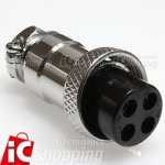
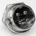
I have only seen the 4 and 5 conductor versions. Which I use...
https://www.parts-express.com/parts-express-cb-mic-plug-4-pin-female--090-535
https://www.parts-express.com/parts-express-cb-mic-plug-4-pin-female--090-535
Good question.
But the glaring error that is Dangerous is the omission of the PE to Chassis Safety connection.
Is there a mains fuse in that IEC input socket?
Yes there is a fuse built into the inlet.

Is not the green wire going from the ring terminal bolted to the chassis and running to the IEC inlet the safety ground?
Rod Elliott also strongly advises against those mini toggle switches on mains.
Power Supply Wiring Guidelines
Power Supply Wiring Guidelines
You have posted the wrong pic. Look at post3455: the second to lasttimed @ 11.50
That is not my (Wntermute) build. Mine is the one I posted just above in the aluminum square case.
just finished my Phonoclone this morning.
What an amazing sound !
Regarding the build (s) in general, I see some where all the wires both input and output are twisted but the power in wires are not, some where just the power ones are twisted and some where just the inputs/outputs are twisted. Is there a consensus on this? Why or why not to twist?
K196 posted pics of his new amplifier Post3055Good question.
But the glaring error that is Dangerous is the omission of the PE to Chassis Safety connection.
Is there a mains fuse in that IEC input socket?
you commented and added a question post3057
I acknowledged your comment and added my comments post3058
and in post3059 I answered your twisted or not question.
You are confused, you have not posted a pic just above k196. I see no pic like that from you since post3021 dated 20th October.
Last edited:
Actually Andrew you sent me a PM regarding my dangerous build. You sent it to Wntrmute. So it seems I am not the "confused one".K196 posted pics of his new amplifier Post3055
you commented and added a question post3057
I acknowledged your comment and added my comments post3058
and in post3059 I answered your twisted or not question.
You are confused, you have not posted a pic just above k196. I see no pic like that from you since post3021 dated 20th October.
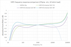
Hello, again. I'm testing the VSPS 300 with the elimination of Allen Wright's 50khz time constant.
My first impressions are that the sound is more pleasant.
But I have noticed that the resistors R5 and R4 in the VSPSX have different values to those that have my VSPS 300. (787K against 732K and 110K against 105K).
This makes the sound misleading and makes it look better ?. Or should I replace the resistors with 787k and 110k ?.
Greetings, Jose.
Quick question: if I was to defeat the AW correction, will it suffice to short across R3, or do I need to eliminate C1 as well?
Hello, again. I'm testing the VSPS 300 with the elimination of Allen Wright's 50khz time constant.
My first impressions are that the sound is more pleasant.
But I have noticed that the resistors R5 and R4 in the VSPSX have different values to those that have my VSPS 300. (787K against 732K and 110K against 105K).
This makes the sound misleading and makes it look better ?. Or should I replace the resistors with 787k and 110k ?.
Greetings, Jose.
The original values for the VSPS were calculated from the RIAA network alone. The VSPSX values were calculated with the LTSpice simulation of the whole circuit, including, critically, the output coupling capacitor C3 and the second LP filter C4.
The improvements seen in the VSPSX response are the result of having more control in the circuit to shape the curve, having the simulation tools available to adjust the values appropriately, and knowing what I want as a high frequency roll-off.
So anyway, no, changing to 787k and 110k will got get you the VSPSX response curve, but it will change the response and therefore sound different. In particular increasing from 732k or 750k to 787k will add more base which you may prefer.
This should tell you what you need to know. Pick your poison.
The VSPSX response is load independent. The bass response of the VSPS curves will will depend a little on the output loading, due to C3 being unbuffered.
The VSPSX response is load independent. The bass response of the VSPS curves will will depend a little on the output loading, due to C3 being unbuffered.
Attachments
Last edited:
Regarding the build (s) in general, I see some where all the wires both input and output are twisted but the power in wires are not, some where just the power ones are twisted and some where just the inputs/outputs are twisted. Is there a consensus on this? Why or why not to twist?
Hello WntrMute2. So there's two of you? I didn't realize. 😛
Unshielded chassis signal and power wiring should always be twisted together with the returns to minimize noise.
In k1965813's build the inputs and outputs are not twisted together, but the distance to the boards are so short, and the PC3 boards have the IN+ and IN- separate by a few cm anyway, that I would not insist. The power wiring is twisted loosely together and kept separate from the signals, so I don't foresee any problems.
Thanks RJM for responding. I keep the VSPS curve with original values and with short circuit in R3.
Along with Marantz PM6006 sounds awesome.
Greetings- Josè
Along with Marantz PM6006 sounds awesome.
Greetings- Josè
Hello WntrMute2. So there's two of you?
Nope just one. Wntrmute2 is the one Wntrmute on this site AFAIK. Sometimes I forget the "2".
I didn't take pictures when I cleared up my project by inserting the bboards into the VSPS circuit. But now that I was doing some adjustments, I took the opportunity to take some that I thought I could post:Should go something like this.
As long as the COM is in electrical contact with COM on the VSPS there is no need to connect the bboards IN- and OUT- terminals. The bboard GND would not normally be connected.

Cable mess is somewhat less messy, as I could eliminate two pairs of leads going back and forth between the VSPS and the buffers.
I did also flip the IEC input socket 180 degrees. Live (yellow lead to the transformer) was really way too close to the bboard for comfort and safety. Now it is earth which comes close, but I guess that's preferable...

In this overview you can see how the bboards go in place of R6, as suggested by Richard.

Another view. Trying the NJM2068DD, but went back to the MUSES8820 which had a better switch on/off behaviour (much less thump).
That's all folks! Just a last peak at the buffers!

🙂
Last edited:
- Home
- Source & Line
- Analogue Source
- The Phonoclone and VSPS PCB Help Desk