Could someone explain me why does the O2 a voltage doubler/half wave rectifier in the power section? Why not a full bridge rectifier?
Also, why does it seem to me that the NJM4556s in the output stage seem...duplicated? Is it just so that they can supply double the amount of power?
One last thing, it seems like the op amps aren't AC coupled. Why? Isn't ac coupling more advantageous?
Thanks in advance!
Also, why does it seem to me that the NJM4556s in the output stage seem...duplicated? Is it just so that they can supply double the amount of power?
An externally hosted image should be here but it was not working when we last tested it.
One last thing, it seems like the op amps aren't AC coupled. Why? Isn't ac coupling more advantageous?
Thanks in advance!
The power supply generates a split rail from a single AC winding and allows one side of that winding to be referred to as 'ground' or zero volts so that precludes using a bridge rectifier in the traditional way. A four terminal bridge rectifier could be fitted and would be configured with each pair of diodes in parallel by connecting together the two AC terminals.
Parallel opamps deliver twice the current.
There is AC coupling from the volume control to the final output stage. When and where and why to include it is down to design choices.
Parallel opamps deliver twice the current.
There is AC coupling from the volume control to the final output stage. When and where and why to include it is down to design choices.
I find it interesting that there is no output decoupling cap. I know it was avoided to help the lower freqs, but how does it solve the DC component on the output?
PS: I'm been thinking for a while on making a DAC based on the PCM2912, mostly as a learning project. What do you guys think if i combined both in the same device? I know i'll have to deal with digital noise/grounding/different power supplies etc.
An output coupling cap would automatically remove any DC present and as an added bonus protect the headphones from any possible DC fault.
There is no (or very little anyway) DC present at any of the opamp outputs because the circuit uses dual supplies (a plus and minus rail). All points within the audio circuit are very close to zero volts DC unless a fault is present.
There is no (or very little anyway) DC present at any of the opamp outputs because the circuit uses dual supplies (a plus and minus rail). All points within the audio circuit are very close to zero volts DC unless a fault is present.
I hope it's okay for me to post this here. I got a used JDS o2 that was working fine until I opened it up to remove some battery connector residue. The right channel no longer works and just crackles when I turn the volume knob. The left channel works fine.
What I did:
-Re-soldered a new ground wire on the input jack since the old one was missing.
-Used white vinegar to remove the battery acid residue from 'BT2' and on 'R16'. I checked that it was dry before turning the amp on again.
What I tried:
-I tried swapping the opamps. 'U3' and 'U4'. It did not make a difference.
-Running the amp without an input still causes the right channel to have crackling noises when I move the volume knob.
I really hope someone can help me since I just got this amp recently. I just want to get it up and running again. I have basic soldering skills and I have a multimeter if you have any suggestions.
Thanks!
Update to previous post.
-I've gone through nwavguy's initial testing and troubleshooting testing. I've been able to verify that all resistance values and voltages values are within spec. So it's at least getting proper DC voltage and the IC's pass this test.
-If I play music then I'm able to plug the headphone in and hear music on both left and right channels. The loud crackling noise is still intermittent on the right channel. The original problem is still there.
What should I be looking at next?
Last edited:
If corrosion has effected R16 then it seems likely your issues could be around that area of the board.
Does the crackling vary in amplitude as you alter the volume control ?
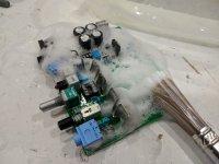
If the board has suffered damage then my own reaction would be to fully wash it using hot water, detergent and a soft brush. Try and keep water out of the volume control and switches. If corrosion has gone under components (IC sockets !) then they may need replacing.
Post #10:
Washing an amplifier board
Does the crackling vary in amplitude as you alter the volume control ?
If the board has suffered damage then my own reaction would be to fully wash it using hot water, detergent and a soft brush. Try and keep water out of the volume control and switches. If corrosion has gone under components (IC sockets !) then they may need replacing.
Post #10:
Washing an amplifier board
Thanks for the response. The crackling does get louder as I increase the volume. I'll try to clean the board tomorrow as you've suggested.
I suspect that I may have shorted the board somehow as it was working perfectly fine right before. In retrospect, I should have discharged the board by pressing the on button first.
I've gone ahead and ordered 4 ICs. Since the voltages measure well would it be safe to replace all the ICs and power up the board or should I take some other precautions?
The fact it is affected by the volume control means the problem is before the output stage (as we suspect).
I would by very surprised if any IC had failed tbh. The problem is more likely to be residual conductive pathways on the board/components/under components from the battery acid rather than a failed part.
I would by very surprised if any IC had failed tbh. The problem is more likely to be residual conductive pathways on the board/components/under components from the battery acid rather than a failed part.
You make a very convincing case. I'll definitely clean the board with extra attention to underneath components.
The fact it is affected by the volume control means the problem is before the output stage (as we suspect).
I would by very surprised if any IC had failed tbh. The problem is more likely to be residual conductive pathways on the board/components/under components from the battery acid rather than a failed part.
Mooly! 😱 Thank you so much! My amp works again!
I never would have tried washing my board without your advice. Seems to go against common knowledge that 'water + electricity = BAD'.
You ended up saving me so much time and headache. If I had kept attacking the problem with the idea that it was a component failure then I'd be going in circles.
Cheers! 😀
Attachments
That's excellent news  and it works nearly every time 😉
I've washed whole panels (dozens and dozens over the years) from the likes of TV's and VCR's and so on.
Just make sure its fully dry before bringing it back into full service. Use paper towel to wick up any moisture from under the sockets and so on and perhaps leave it without batteries fitted for a day or two to allow all moisture to evaporate. As long as you are happy its dry 🙂
and it works nearly every time 😉I've washed whole panels (dozens and dozens over the years) from the likes of TV's and VCR's and so on.
Just make sure its fully dry before bringing it back into full service. Use paper towel to wick up any moisture from under the sockets and so on and perhaps leave it without batteries fitted for a day or two to allow all moisture to evaporate. As long as you are happy its dry 🙂
I didn't want to make the situation worse so I spent a lot of time with the drying part. I actually took the ICs out so that I could run water through the sockets to drive out whatever was potentially there. Used an air compressor liberally and let the board dry overnight with a fan over it.
You managed to help me fix my amp and teach me a new technique that I can use in the future.
You managed to help me fix my amp and teach me a new technique that I can use in the future.
Saw this contest.
2nd PCB DESIGN CONTEST
So I'm thinking of building an O2 desktop variant PCB using 2X 15V SMPS on a 100mm by 100mm board. Half of the circuit will be remove, retaining the op amps, LM317+337 and volume pot. In future whoever would like to DIY an O2 could just simply download the file for free and order the PCB online.
Let me get the schematic out first.
Jason, sounds perfect, but what would be the schematic, please? Caps will have a better ripple and voltage, also what case will be used? A different power transformer as well, right?
From personal experience, JRC/NJM 7815/7915 are having a lower noise and better ripple rejection than LM317/337 and it would also be easier to implement.
I think agdr did this mod in a previous post, I think it was +/-15V with different caps on rails and RC filter (he cut the PCB on the back), but having a new PCB might be a good idea, especially if it can fit inside original O2’s case (of possible).
Jason, sounds perfect, but what would be the schematic, please? Caps will have a better ripple and voltage, also what case will be used? A different power transformer as well, right?
From personal experience, JRC/NJM 7815/7915 are having a lower noise and better ripple rejection than LM317/337 and it would also be easier to implement.
I think agdr did this mod in a previous post, I think it was +/-15V with different caps on rails and RC filter (he cut the PCB on the back), but having a new PCB might be a good idea, especially if it can fit inside original O2’s case (of possible).
Hi Raoul.
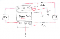
I'm still building from scratch using Altium so won't be so quick in outing the sch. The caps I'll be using low impedance version, rated 25V for the 15V supply and rated 16V for the 12V supply. I will implement 2 footprint in my design to cater either 317/337 or 7812/7912, see attachment.
The case I'll be using is meant for 100mm x 100mm PCB, which is plentiful in China. Since it's meant for desktop, I would not want too low of the height on the case which I prefer to put bigger cap. O2 original PCB is 100mm x 80mm, case 100x80x30mm.
The +-15V supplies will be from 2 15V SMPS, connect them in series to get +-15V. Which I believe should be much easier to get nowadays. Or choose 2 wall outlet that output 13.5V ac, will build a rectifier circuit inside. Still thinking should I put a safety relay when both adapter is not plug in.
Attachments
Last edited:
SMPS? Hmmm...hope you can find some low-noise supplies, wonring already how will ripple&noise look under the scope. 🙂
What are you thinking to place in output buffers?
What are you thinking to place in output buffers?
- Home
- Amplifiers
- Headphone Systems
- The Objective2 (O2) Headphone Amp DIY Project