hey guys, dusted off the old O2/ODAC rev b I built back in 2012, planning on using it to power my Fostex T50-RP (45Ω). I've wired RCA outs in which i plan on feeding to an Emotiva XPA power amp essentially using it as a preamp/attentuator.
Im placing an order for some upgraded BOM materials and am wondering if theres a newer/more suited output OP AMP(s) for this application.
Im placing an order for some upgraded BOM materials and am wondering if theres a newer/more suited output OP AMP(s) for this application.
There is anecdotal evidence of people having put in OPA1688s on adapter boards. Not sure how well operation has been verified with these, however - having a few Rs and Cs to make test loads and a scope on hand may be a good idea.
Thanks for the response, searching for said adapter boards hasnt turned up any other suppliers than AGDR audio which store isnt working.
Any other sources?
Any other sources?
I very much appreciate your help, and have made good progress, but have run into another problem. Now all of my DC voltages match the values in NwAvGuy's O2 Details documentation (p19 of 72). However, as I finished the measurements I noticed that U5 and U6 were both getting very hot. Any ideas here?
The regulators really should only be warm I would have thought... but heat is difficult to describe.
1/ Is the amp working correctly now as far as playing audio?
2/ Confirm the DC output voltage on pins 1 and 7 of U3 and U4 is zero.
3/ Confirm all the of the IC's are running cool/cold to the touch.
If all that is OK then there may not actually be a problem. Your wall wart provided around 18 volts AC as I recall and that will give around -/+26 volts DC applied to the regulators. That means each regulator has to drop 14 volts (26-12) and if we say the total current draw is (guessing) 25ma (and more if you have rechargeable fitted and they are drawing current) then we are up to 400 milliwatts dissipation in each regulator. It doesn't sound much but it's enough to significantly heat the device.
Haven't tried it with input and headphones yet. U4 measurements are good, no DC voltage on pins 1 and 7. But pins 1 and 7 on U3 both measure -11.8 vdc! When I took these measurements, the O2 was on for about three minutes and the regulators were just warm.
U3 appears to have a problem.
Check the voltage on all pins of the chip itself (not the socket).
First make sure the +12 volts is present on pin 8 as a missing supply would give that fault.
The input pins (3 and 5) should be very close to zero. Pins 2 and 6 will just follow the output pins as they are linked but it is always worth still measuring them in case of any weird board issues.
The chip is the last suspect but if you are unsure then you can always swap it with U4 as a quick confirmation.
Voltage on pin 8 of U3 is +11.7 VDC. Pins 3 and 5 are -11.67 VDC; all the other pins (1, 2, 4, 6 and 7) are -11.79 VDC. Both regulators were again not warm after these measurements, probably 10 minutes on. I have another chip I can replace it with if you think it is safe to try that.
Chips are always the last suspects unless something 'bad' has happened to them such as over volts or reverse polarity.
If you remove the chip from the socket and then re-measure the voltages on the empty socket pins then you should only see the +12 and -12 on pins 8 and 4 respectively. All the other pins must be zero.
If they are then try a new chip.
If they are not then you have a short or solder blob somewhere such as between pins 3 and 4.
The voltages are good
Pins 3 and 5 resistance checks suggest a problem. 11 ohms is very low. Look at the circuit and try and follow this...
You are using J2 ground (that is OK to use) but only seeing 11 ohms to pins 3 and 5. So a couple of things to check are:
1/ That you still read 11 ohms to the relevant IC socket pins with the IC removed. That's an important check because I don't know how your meter responds to the presence of other in circuit parts like the chip that may appear in parallel to what we want to measure.
2/ We also need to be sure your meter is reading correctly and that you are interpreting the results correctly. So as a quick check your meter should read 1 ohm if you quickly measure those resistors at the output IC's.
3/ Assuming the 11 ohms is a real result you now need to check the resistance between ground and pins 1 and 3 of plug P1.
Keep looking at the circuit.
If you have 11 ohms at pin 3 and 5 you should see 11 ohms PLUS the value of the resistor R7 or R3 added to the result.
Fwiw, if you can't see any obvious problems anywhere then the most like areas are around those sockets.
A definitive test would be to lift the resistors R3 and R7 and to feed your audio directly into pins 3 and 5 thus eliminating all the sockets etc.

Ok, so, here we go.
Output resistors measure 1ohm, so meter is accurate.
I was wrong on the 11ohm. tried this again, was measuring 9.95 kOhm. This is the same for with the IC in or out.
R3 and R7 both measure at 0.273-0.275 kOhm
Pins 1 and 3 of P1 both measure at 10.22-10.23.
Sounds like I'll need to try feeding the audio directly into pins 3 and 5.
9.95k sounds correct and will be the value of R20 and R14 which tie pins 3 and 5 to ground. So that is a good result and seems to show no shorts on the opamp input side of things.
If you feed audio straight into pin 3 (or pin 5) then you should hear normal audio in the appropriate channel only. That will prove everything from pins 3 and 5 onward is OK.
If that is good then you should also get the same audio result feeding the signal into pins 1 and 3 of connector P1.
I think we can rule out a short anywhere on the input because your reading of 10.23k etc on P1 rules that out. That really only leaves the other option... broken print somewhere along those lines from the input sockets to R3 and R7.
I closely examined the bottom of the board with a stereo microscope at 15x and tidied up a few things. After removing the chip, voltages at all sockets were correct, so I inserted a new chip, added input and headphones and now have music! Thanks again for your expert help and quick responses.
 that's good. Pleased to hear that you sorted it.
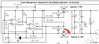
did some upgrades on the O2 and powered it up, was getting no sound. Found a small short over D(rain?) and G(ate?) on Q2. Upon powering back on same deal.
As im not familiar with mosfets is there anything else that may have been affected up/down stream? Im unable to easily remove U1,2,3,4 to test as they dont have sockets.
Thanks!
As im not familiar with mosfets is there anything else that may have been affected up/down stream? Im unable to easily remove U1,2,3,4 to test as they dont have sockets.
Thanks!
Attachments
Last edited:
If the supplies coming out of the FET's are correct (so correct supplies on all opamps) then your no sound issues lie elsewhere.
is there a reference for voltages with all ops in? Or do i need to start de-soldering? any theory on whether the short across the drain and gate ruin Q2?
You should have +12 volts on pin 8 of all the opamps and -12 volts on pin 4 of them all. Every other pin on the opamp should read zero volts DC.
Measure from the main audio ground such as the ground tab of the input sockets. Ground (gnd) is marked at many locations on the 02 circuit diagram. Any of those points are OK to work from.
Measure from the main audio ground such as the ground tab of the input sockets. Ground (gnd) is marked at many locations on the 02 circuit diagram. Any of those points are OK to work from.
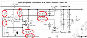
Thanks for the insight Mooly. Only opamp getting +/-12 was over U2. Diagnosed all the resistors in the power management section are open ended.
Ill order the entire power management replacements but any other components downstream damaged do you think?
Ill order the entire power management replacements but any other components downstream damaged do you think?
Attachments
- Home
- Amplifiers
- Headphone Systems
- The Objective2 (O2) Headphone Amp DIY Project