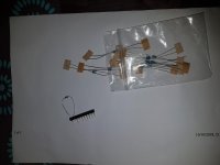
Hi all, I notice in the kit that came from Head'n'Hifi that there are some pins that presumably one solders into place and then the gain resistors push in place and can allow one to experiment with different gain values.
So: across which resistors do these pins get installed, and is there a list somewhere where the combinations of resistors show the gains?
Please don't fling equations at me cos I don't understand them.
Thanks.
So: across which resistors do these pins get installed, and is there a list somewhere where the combinations of resistors show the gains?
Please don't fling equations at me cos I don't understand them.
Thanks.
All you are doing to change the gain is connecting a resistor from pin 2 and pin 6 of that front end opamp to ground.
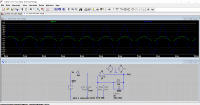
The formula is easy, divide the value of R16 by the value of the resistor you add to ground and then add 1 to the result. So with R16 fixed at 1.5k and lets say we pick 270 ohms for our resistor to ground we get 1500/270 which is 5.55. Add 1 and we 6.55.
Does it work... lets see. Here we have 1 volt peak applied, and the output is 6.55 volts. It works 🙂
Attachments
Thanks Mooly, whats the front end op amp, where is it and how and where do I attach the resistor, and where are pins 2 and 6?All you are doing to change the gain is connecting a resistor from pin 2 and pin 6 of that front end opamp to ground.
The formula is easy, divide the value of R16 by the value of the resistor you add to ground and then add 1 to the result. So with R16 fixed at 1.5k and lets say we pick 270 ohms for our resistor to ground we get 1500/270 which is 5.55. Add 1 and we 6.55.
Does it work... lets see. Here we have 1 volt peak applied, and the output is 6.55 volts. It works 🙂
It would be good if anyone has a photo of what Mooly helpfully just suggested, as I have no idea what he's talking about.
Also that only describes one end of S2, there's another gain setting needed (for when the switch is depressed)

Many thanks again Mooly, that shows me that the kit as supplied already has those components laid out and marked to give 2.5x and 6.5x.These are the gain setting resistors (circled). You can fit whatever values suit your needs. Here the switch selects either 1k or 274 ohms giving gains of 2.5 or 6.47
So what's this:
Attachments
I have no idea where those parts fit into the scheme of things I'm afraid. As I keep saying in the thread, I have never seen, heard or built an 02. I just work from the published circuit details for helping out with fault-finding.
That's for making sockets for passives like the gain setting resistors, in case you want those swappable.
Yes I know Mooly, sorry to have hassled you.I have no idea where those parts fit into the scheme of things I'm afraid. As I keep saying in the thread, I have never seen, heard or built an 02. I just work from the published circuit details for helping out with fault-finding.
It's just, unlike the ACA, there's apparently no build blog, I'm not an electronics person by a long shot, but I like building things that have a use, and generally I'm quite good at it.
Where I fall down is the maths, I just don't understand it, even wiring diagrams I can't follow as I have some sort of disability in that area.
So thanks for the help you've given, I think I can build now with that info.
sgrossklass, I'm guessing by your comment that the resistors that Mooly mentioned would be swappable if I use those sockets first, then plug the resistors into them.
NwAvGuy's own building instructions (incl. details about gain resistors and Initial DIY testing) is also pretty thorough. I did build my first O2 following that guide.
NwAvGuy: O2 Details
NwAvGuy: O2 Details
Yes I know Mooly, sorry to have hassled you.
It's just, unlike the ACA, there's apparently no build blog, I'm not an electronics person by a long shot, but I like building things that have a use, and generally I'm quite good at it.
Where I fall down is the maths, I just don't understand it, even wiring diagrams I can't follow as I have some sort of disability in that area.
So thanks for the help you've given, I think I can build now with that info.
sgrossklass, I'm guessing by your comment that the resistors that Mooly mentioned would be swappable if I use those sockets first, then plug the resistors into them.
I'm guessing by your comment that the resistors that Mooly mentioned would be swappable if I use those sockets first, then plug the resistors into them.
Copied from NWAVGuy:
Optional Gain Resistor Pin Sockets – There’s an optional part in the BOM for allowing the gain resistors (R17, R21, R19, R23) to be replaced without soldering. These “SIP” pin sockets are bit tricky to align correctly and can be installed in pairs.
THE GAIN RESISTORS: Before you solder in the four gain resistors by the gain switch, you might want to consider different gains than the approximately 2.5X and 6.5X default values. You want just enough gain so typical music plays loudly enough with your headphones and source and not much more. Extra gain means using less of the volume control’s range, more noise, more distortion, and makes accidental headphone damage more likely. Here’s what you need to know about calculating gain:
- Lower Is Safer - Lower gain settings make the amp less likely to damage headphones by limiting the maximum output voltage to only approximately what’s needed.
- Lower is Cleaner – As shown in the first article, there’s a slight increase in distortion, especially at high frequencies at higher gain settings. Lower gains also result in lower noise.
- Resistor Values – The O2’s gain (for one channel) is:
Low Gain Ratio = 1 + R16/R17
High Gain Ratio = 1 + R16/R19
Voltage Gain in dB = 20 * Log(Gain Ratio) - Example – The standard amp has R16=1500 and R17= 1K so 1 + 1500/1000 = 2.5X. And 20*Log(2.5) = ~ 8 dB.
- Feedback Impedance – For many reasons it’s generally best to leave R16 and R22 at 1500 ohms unless U1 is replaced with a weak op amp that can’t handle a 1.5K load.
- See The BOM - Gain resistors are pre-calculated in the BOM parts list for gains of 2X – 12X. For 1X gain just leave out the gain resistors (or clip one end if they’re already installed)
Thanks, I've seen that but it's no build blog for us novices in the way that the ACA blog is.NwAvGuy's own building instructions (incl. details about gain resistors and Initial DIY testing) is also pretty thorough. I did build my first O2 following that guide.
NwAvGuy: O2 Details
I don't expect "solder this here, and that there" but staged photos of the build would help enormously, especially where remote mounting of components is concerned.
It looks like this forum has made that leap of: if you're building this, you understand electronics. Not so for all of us.
If there was a blog of some sort, or even if people that have built this posted pics (especially if remote mounted components are used), it would make it much easier.
Copied from NWAVGuy:
Optional Gain Resistor Pin Sockets – There’s an optional part in the BOM for allowing the gain resistors (R17, R21, R19, R23) to be replaced without soldering. These “SIP” pin sockets are bit tricky to align correctly and can be installed in pairs.
THE GAIN RESISTORS: Before you solder in the four gain resistors by the gain switch, you might want to consider different gains than the approximately 2.5X and 6.5X default values. You want just enough gain so typical music plays loudly enough with your headphones and source and not much more. Extra gain means using less of the volume control’s range, more noise, more distortion, and makes accidental headphone damage more likely. Here’s what you need to know about calculating gain:
- Lower Is Safer - Lower gain settings make the amp less likely to damage headphones by limiting the maximum output voltage to only approximately what’s needed.
- Lower is Cleaner – As shown in the first article, there’s a slight increase in distortion, especially at high frequencies at higher gain settings. Lower gains also result in lower noise.
- Resistor Values – The O2’s gain (for one channel) is:
Low Gain Ratio = 1 + R16/R17
High Gain Ratio = 1 + R16/R19
Voltage Gain in dB = 20 * Log(Gain Ratio)- Example – The standard amp has R16=1500 and R17= 1K so 1 + 1500/1000 = 2.5X. And 20*Log(2.5) = ~ 8 dB.
- Feedback Impedance – For many reasons it’s generally best to leave R16 and R22 at 1500 ohms unless U1 is replaced with a weak op amp that can’t handle a 1.5K load.
- See The BOM - Gain resistors are pre-calculated in the BOM parts list for gains of 2X – 12X. For 1X gain just leave out the gain resistors (or clip one end if they’re already installed)
Thanks Neal, I think it's worth trying to fit those as you mentioned.
This is because I intend to use this as a headphone amp and a preamplifier for the ACA.
I'm hoping that I will get away with unity on the ACA and leave the pushed-in button for gain for my headphones.
Using the SIP sovkets will enable me to experiment.
Power supply
Hi, I bought a power supply specifically for this Objective 2 amp, it says 15v secondary but reads under no-load 18.24v.
Should I be concerned or will it drop under the requisite load?
Hi, I bought a power supply specifically for this Objective 2 amp, it says 15v secondary but reads under no-load 18.24v.
Should I be concerned or will it drop under the requisite load?
If it says "AC 15V" its ok (Beware, its not DC15V!), O2 is not a heavy current load so Voltage drop would be minimal AC 18.24V is within tolerance limits.
Thanks Availlyrics, it IS AC, phew!If it says "AC 15V" its ok (Beware, its not DC15V!), O2 is not a heavy current load so Voltage drop would be minimal AC 18.24V is within tolerance limits.
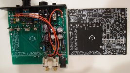
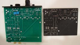
I opened up my massdrop O2 and have attached some pics. Looks to be identical with an add-on to the board for the rear connections. I was surprised to see the battery connectors on it, massdrop does not advertise these as portable. I did not test to see if there was any voltage there, but I don't see why there would not be. Nichicon caps throughout. I like this amp, dead quiet, though I have occasionally experienced some distortion, but that may very well be from other components in the chain.
Attachments
Very interesting!
First time I've seen such a variation. The protuding added PCB estate at the back is actually quite clever. Looks like it has got input connections as well.
Looks also like C8/9 and the 4556's decoupling caps swapped places to accommodate the output jack.
First time I've seen such a variation. The protuding added PCB estate at the back is actually quite clever. Looks like it has got input connections as well.
Looks also like C8/9 and the 4556's decoupling caps swapped places to accommodate the output jack.
I was surprised to see the battery connectors on it, massdrop does not advertise these as portable.
Actually they do! 😉
(PS. Well... to be fair, they do not advertise them as portable, but as battery powered)
Attachments
[...] I like this amp, dead quiet, though I have occasionally experienced some distortion, but that may very well be from other components in the chain.
Be sure to not exceed gain of 3.5X, in your case 2.5X or 3.3X, depending what version you were choosing.
Missing component from BOM
Hi all, I had ordered two pcb's for above and sourced another lot of components from Mouser UK. But there was one component that was not available in this country- Everlight High Efficiency Red Right Angle LED Indicator
Part No: MV5764.MP4B
Is there an alternative available over here?
TIA
Hi all, I had ordered two pcb's for above and sourced another lot of components from Mouser UK. But there was one component that was not available in this country- Everlight High Efficiency Red Right Angle LED Indicator
Part No: MV5764.MP4B
Is there an alternative available over here?
TIA
- Home
- Amplifiers
- Headphone Systems
- The Objective2 (O2) Headphone Amp DIY Project