here's another material that would work excellant when lamentating sheets.
0 005" Unclad 360IN² FR4 PCB Insulator Insulating Sheet | eBay
I'm trying to find the supplier of the thicker glass boards I have. 12" x 24" 0.020 and 0.025 thickness used for RC jet construction. As this industry has flip flopped do to the economy don't know if the company is still around. Over in Lakeland FL. Near the airport, where Sun 'n Fun and RC Jets Show fly.
Found it... G-10 Fiberglass sheets
Greetings xrk,
I have a couple of Mark Audio CHP-70's and wondering what you think about trying them in this design?
Thank you,
Marko
I have a couple of Mark Audio CHP-70's and wondering what you think about trying them in this design?
Thank you,
Marko
Greetings xrk,
I have a couple of Mark Audio CHP-70's and wondering what you think about trying them in this design?
Thank you,
Marko
The Nautaloss essentially acts as a back wave black hole so should work for just about any driver provided that the volume is sufficiently large to match Vas.
The Nautaloss essentially acts as a back wave black hole so should work for just about any driver provided that the volume is sufficiently large to match Vas.
Thought over that your step response plots are very nice, is the black hole mentioned part of this or is there else explanation.
The DEQ2496 result delayed, in next days i pop up.
Thanks xrk, I'll go back through the thread and see what I can gather about spiral size and required Vas. If more is needed, I'll just factor up the proportions accordingly.
You've sure done some great work on this forum with all these foam core projects! Thank you.
Kindest,
Marko
You've sure done some great work on this forum with all these foam core projects! Thank you.
Kindest,
Marko
Thought over that your step response plots are very nice, is the black hole mentioned part of this or is there else explanation.
The DEQ2496 result delayed, in next days i pop up.
The impulse response is clean because the response of the Vifa is very smooth and flat - in large part due to the fact that back reflections don't show up on the cone output.
Thanks xrk, I'll go back through the thread and see what I can gather about spiral size and required Vas. If more is needed, I'll just factor up the proportions accordingly.
You've sure done some great work on this forum with all these foam core projects! Thank you.
Kindest,
Marko
An easy way is to run WinISD or your favorite speaker program in sealed cabinet. See what that volume is and make the Nautaloss at least that big in volume. Can be bigger - not a problem but if too small will limit low frequency extension and driver may sound a bit congested.
Nuataloss I with CHP-70
I think you mean CHP-70A (paper cones)? http://www.madisound.com/store/manuals/CHP-70%20Gen.2%20natural%20Eng.pdf
They work very well in the same dimensions as the Nautaloss I built. This is the single driver version. Here are the simulations (room reflections turned off).
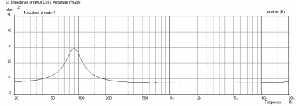
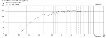
Plots: SPL vs Freq at 2.83v and 1 meter (full range no filters), Cone Displacement at xmax (with -12dB/oct Butterworth high pass at 200 Hz), SPL vs Freq corresponding to xmax at 37 volts rms (with high pass filter), Impulse response with high pass filter, and Impedance. Last plot is what it might look like with room reflections turned on (62 in from back wall, 72 in from side wall, 39 in high on a stand).
You will need to EQ some baffle step correction from 1.5 kHz and below - however when I look at the the measured freq response curves, it looks like the driver has a built in baffle step compensation for off-axis listening (20 deg or so).
Looks like a great candidate for a Nautaloss and with the 4 mm xmax, you can achieve some pretty high SPL's of 109 dB at 1 m - suitable for a studio monitor. Although this power level cannot be sustained - just dynamic peaks as it corresponds to 170 watts of power.
Good luck!
Greetings xrk,
I have a couple of Mark Audio CHP-70's and wondering what you think about trying them in this design?
Thank you,
Marko
I think you mean CHP-70A (paper cones)? http://www.madisound.com/store/manuals/CHP-70%20Gen.2%20natural%20Eng.pdf
They work very well in the same dimensions as the Nautaloss I built. This is the single driver version. Here are the simulations (room reflections turned off).
Plots: SPL vs Freq at 2.83v and 1 meter (full range no filters), Cone Displacement at xmax (with -12dB/oct Butterworth high pass at 200 Hz), SPL vs Freq corresponding to xmax at 37 volts rms (with high pass filter), Impulse response with high pass filter, and Impedance. Last plot is what it might look like with room reflections turned on (62 in from back wall, 72 in from side wall, 39 in high on a stand).
You will need to EQ some baffle step correction from 1.5 kHz and below - however when I look at the the measured freq response curves, it looks like the driver has a built in baffle step compensation for off-axis listening (20 deg or so).
Looks like a great candidate for a Nautaloss and with the 4 mm xmax, you can achieve some pretty high SPL's of 109 dB at 1 m - suitable for a studio monitor. Although this power level cannot be sustained - just dynamic peaks as it corresponds to 170 watts of power.
Good luck!
Attachments
-
 Nautaloss-I-CHR70P-Freq-1m-1watt.png21.9 KB · Views: 471
 -
 Nautaloss-I-CHR70P-xmax-Displ.png23.3 KB · Views: 465
 -
 Nautaloss-I-CHR70P-Freq-1m-max-SPL.png22.1 KB · Views: 455
 -
 Nautaloss-I-CHR70P-Impulse-max-SPL.png12.9 KB · Views: 458
 -
 Nautaloss-I-CHR70P-Impedance.png21.6 KB · Views: 468
 -
 Nautaloss-I-CHR70P-Freq-1m-max-SPL-with-Reflections.png23.1 KB · Views: 130
Last edited:
I would exchange them to get the best. 😉I am bi-amping with a Yamaha RX360 (45 w/ch) amp for subs and a home built TPA3116D2 class D amp for the tops (40 w/ch).
xrk, very kind of you to run the sims, thank you.
As I continue working my way up the very “tall” learning curve...a couple of thoughts.
Looking at the current CHP 70, I think my drivers might be an earlier model. They are tan with a series of dots around the face (thinking that your sims would be relatively similar if run with the older version). I picked up a used pair of Frugal Horns a while back after reading so many good things about them. My interest in trying a different enclosure is not so much to improve on an already excellent design as it is to understand more about the effects of active crossing and filtering.
So, using an active unit, based on your charts, I’d see what happens with attenuating somewhere in the 400-500hz and up, then crossing a sub in at around 100hz. I know this likely goes against the concept of FR designs but what the ha’… it’s all in the fun of learning.
Thanks again for your input 🙂
Marko
Those dots mean that it is a special Enabled driver - nice... Your sub and your full range XO should overlap in such a way that there is not a gap or dip in the response. If you set the high pass on the full range at 400 Hz and the low pass on the sub at 100 Hz there is about 100 to 400 Hz gap (depending on how steep your XO is). Probably better to set it at about between 200 Hz and 300 Hz but match them for a smooth transition or crossover point. It will not matter much if it is an older or newer version as they are close enough for this type of alignment.
Study of the effect of miniDSP on SQ
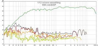
Someone on another thread suggested that that the miniDSP alters the sound quality compared to not using one. The comment was that when used with an Enabled Alpair 10 full range driver - there was a 'veil' that appeared. The test to see if the miniDSP affects the sound quality would be to set the miniDSP to serve as just a high pass filter with the XO point set low enough not to impact the full range driver's main bandwidth.
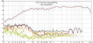
I set out to test this with the Nautaloss I by measuring the response in the nearfield with and without the miniDSP. For the case with the miniDSP, I set a LR -12dB/oct high pass filter at 50 Hz. For the case without, I went straight from the PC lineout to the TPA3116D2 amp. I adjusted the output levels to match. The results are interesting...
Here is the Frequency Response and Phase for the no miniDSP case:
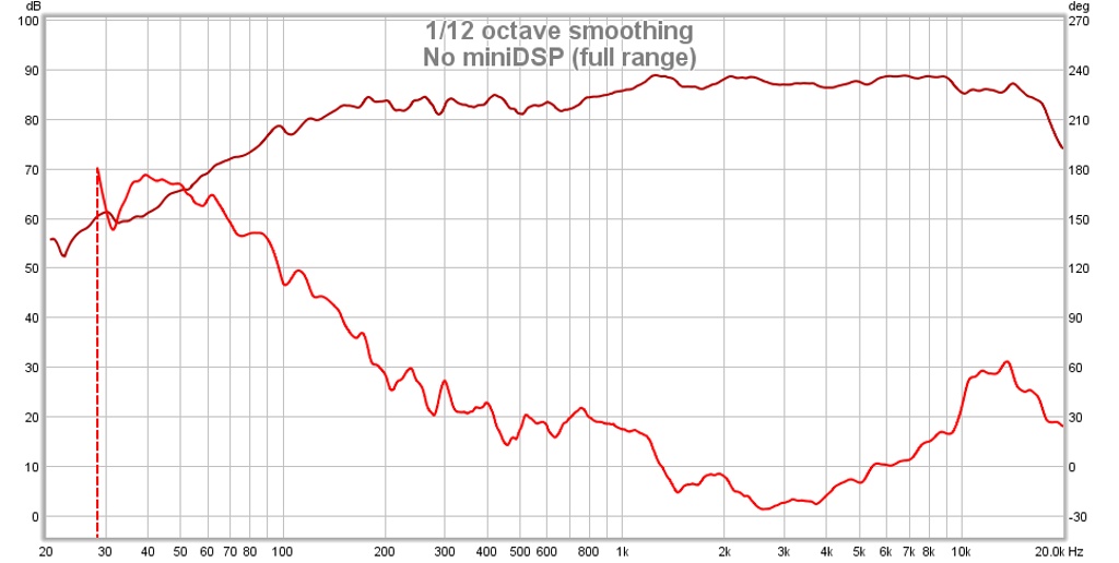
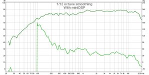
Here is the Frequency Response and Phase for the with miniDSP case - not the phase linearity and flatness is actually improved (by factor of 2x!) with the miniDSP. Of course there is phase wrap at the around the XO point which was expected as this is an IIR filter:
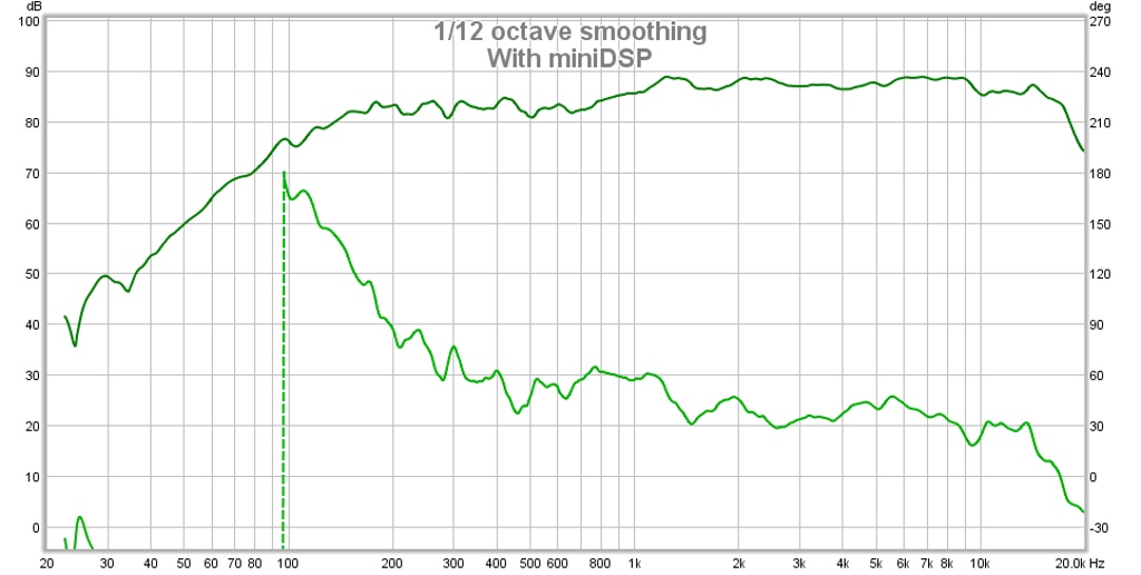
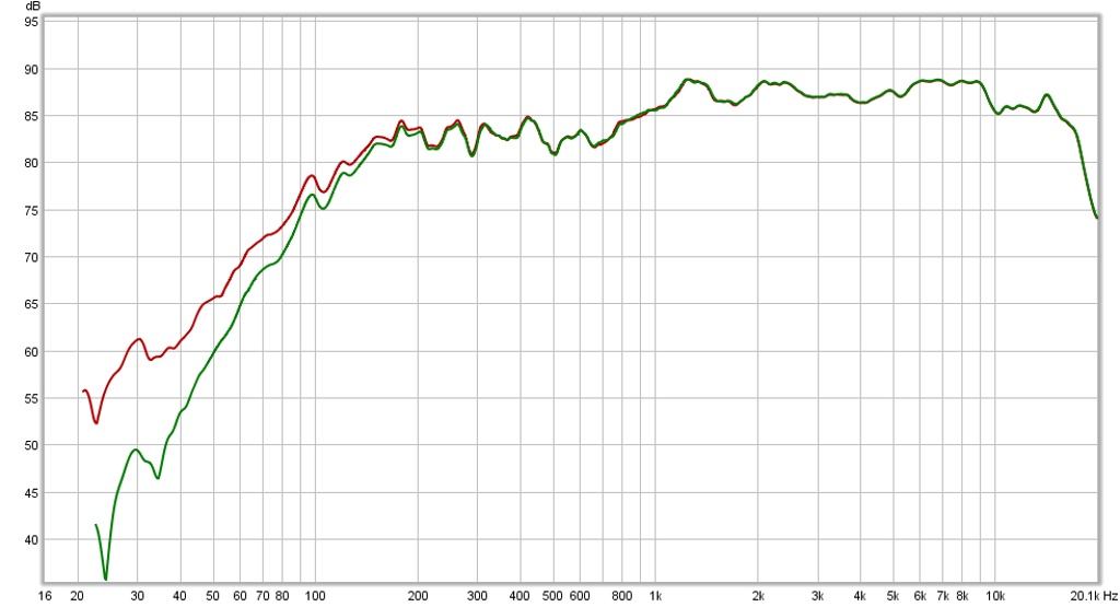
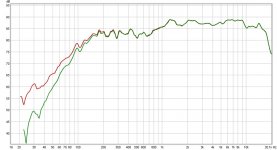
Even with the XO at 50 Hz, there still is residual impact to the fall-off from below 200 Hz that can be seen in the side by side comparison:
Here is the Distortion (up to 5th harmonic) for the no miniDSP case:

Here is the Distortion for the with miniDSP case - at lower frequencies the distortion appears to have increased but this is not important as the main pass band of interest is above 200 Hz:

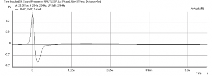
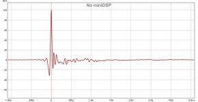
Here is the Impulse Response for the no miniDSP case - very clean with a minimal overshoot:

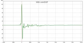
Here is the Impulse Response for the with miniDSP case - there is a substantial overshoot, but very short in time duration. I wonder how this shows up on sound quality when one listens to it? Does it sound excessively sibilant or too bright?
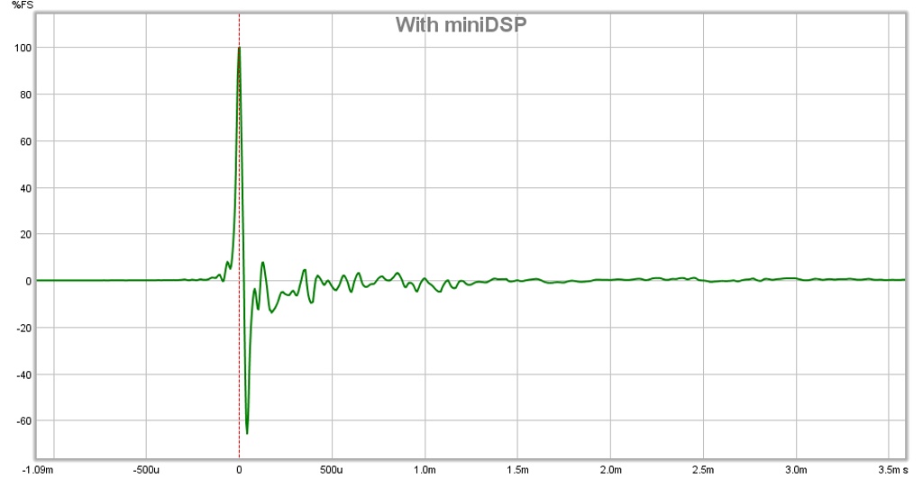
How do they sound with and without? I tested several different CD's with different genres, and styles. I really could not tell a difference - the difference in IR was not perceptible to my ears. Maybe it makes a difference with Enabled drivers?
Someone on another thread suggested that that the miniDSP alters the sound quality compared to not using one. The comment was that when used with an Enabled Alpair 10 full range driver - there was a 'veil' that appeared. The test to see if the miniDSP affects the sound quality would be to set the miniDSP to serve as just a high pass filter with the XO point set low enough not to impact the full range driver's main bandwidth.
I set out to test this with the Nautaloss I by measuring the response in the nearfield with and without the miniDSP. For the case with the miniDSP, I set a LR -12dB/oct high pass filter at 50 Hz. For the case without, I went straight from the PC lineout to the TPA3116D2 amp. I adjusted the output levels to match. The results are interesting...
Here is the Frequency Response and Phase for the no miniDSP case:
Here is the Frequency Response and Phase for the with miniDSP case - not the phase linearity and flatness is actually improved (by factor of 2x!) with the miniDSP. Of course there is phase wrap at the around the XO point which was expected as this is an IIR filter:
Even with the XO at 50 Hz, there still is residual impact to the fall-off from below 200 Hz that can be seen in the side by side comparison:
Here is the Distortion (up to 5th harmonic) for the no miniDSP case:
Here is the Distortion for the with miniDSP case - at lower frequencies the distortion appears to have increased but this is not important as the main pass band of interest is above 200 Hz:
Here is the Impulse Response for the no miniDSP case - very clean with a minimal overshoot:
Here is the Impulse Response for the with miniDSP case - there is a substantial overshoot, but very short in time duration. I wonder how this shows up on sound quality when one listens to it? Does it sound excessively sibilant or too bright?
How do they sound with and without? I tested several different CD's with different genres, and styles. I really could not tell a difference - the difference in IR was not perceptible to my ears. Maybe it makes a difference with Enabled drivers?
Attachments
-
 no-dsp-ir-nautaloss-i.jpg70 KB · Views: 3,067
 -
 with-minidsp-thd-nautaloss-i.jpg137.9 KB · Views: 1,113
 -
 no-dsp-thd-nautaloss-i.jpg137.1 KB · Views: 1,119
 -
 freq-resp-compare-nautaloss-i.jpg103.4 KB · Views: 1,117
 -
 with-minidsp-freq-resp-phase-nautaloss-i.jpg112.4 KB · Views: 1,423
 -
 no-dsp-freq-resp-phase-nautaloss-i.jpg113.1 KB · Views: 2,347
 -
 with-minidsp-ir-nautaloss-i.jpg69.2 KB · Views: 3,014
Last edited:
You should compare electrical signals to remove any effect of mic room placement issues. This would give you a baseline, a reference to evaluate the before/after. Otherwise it's difficult to make any conclusions from this
What electrical signals are you suggesting should be compared ? You mean signal from miniDSP direct to ADC? I am using a USB mic so ADC is not separate. Isn't it the point to see if differences can be heard or measured at the speaker?
What electrical signals are you suggesting should be compared ? You mean signal from miniDSP direct to ADC? I am using a USB mic so ADC is not separate. Isn't it the point to see if differences can be heard or measured at the speaker?
Amp out or Amp in will work. The latter will not show you how the amp reacts to the speaker load
Otherwise it's difficult to make any conclusions from this
I don't see why you say it's difficult to make any conclusions. The room effect is identical on both because the mic and speaker were untouched. The only change was how the signal to the amp was routed. Besides, room effects are below 500 Hz and the complaint from the member who suggested this test said that a HF 'veil' was present when the miniDSP is in the path. Clearly, the measurements show a perfect match on the frequency response from 200 Hz up to 20 kHz - the only difference being an improved phase linearity at expense of impulse response overshoot. From this, I can conclude from this measurement and my own ears that the miniDSP causes no noticeable degradation in the HF sound quality associated with the key frequency band associated with imaging, localization, and "airiness" as some people call it. Definitely no sign of a HF "veil" and if anything, the impulse overshoot may be heard (if you can detect it audibly) as a sharpness in percussion instruments - just the opposite of a veil.
I don't have an ADC input that can measure amplifier voltage transients and waveforms (an O-scope basically) and don't think it will give me any more info than what I am looking for here - measurable acoustic differences at the speaker output.
THank you for trying xrk. I will willingly admit that it could be either psychoacoustic or poor psu implementation. I asked a couple other fellows to listen and see if they heard a difference, not telling them anything about what was being done. POooooor abx testing, i know. Both identified when the DSP was inserted, post test. IT was tried on more than one set of speakers, exactly as i recommended to you. I am in no way claiming any thing about the DSP. This simply makes me want to attach it to proper PSU.
- Home
- Loudspeakers
- Full Range
- The Nautaloss Ref Monitor