xrk971,
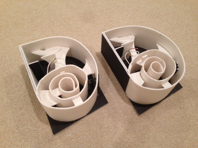
Any photos of the Nautaloss I showing the internal bracing? (unstuffed). Or is it just the three braces?
It is basically same on the II. Look at post 84. On the I I had a few more braces between the two sides from the mouth down to 90 deg into the spiral. Not needed but can't hurt. I was low on hot melt glue so skipped those.
Last edited:
Nautaloss II - Measurements with REW (Including Waterfall)
I discovered the wonderful REW software which performs measurements that include waterfall and spectrograms. In case you have not seen REW, it is cross-platform (PC, OSX, and Linux) as it is written in Java and is available from here for free: REW - Room EQ Wizard Room Acoustics Software
I repeated my measurements with the UMM-6 mic and REW used the calibration file from the manufacturer of the microphone to provide measurements in actual dB SPL.
Here are the measurements again at 12 in from speaker with mic 39 in above floor, a home-built Texas Instruments TPA3116D2 amp (powered by 19 volt laptop SMPS), and PC is now a small HP Mini 110 netbook (which has a better sound card with less distortion than my previous laptop).
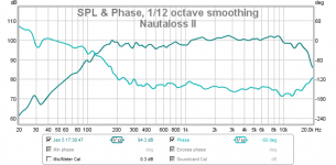
Frequency Response and Phase:

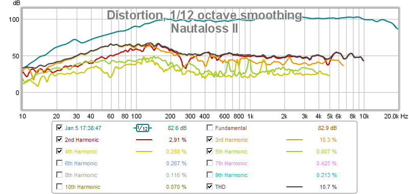
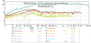
Harmonic Distortion:
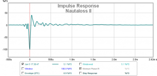
Impulse Response (signal needs to be inverted next time...):

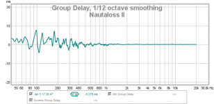
Group Delay:

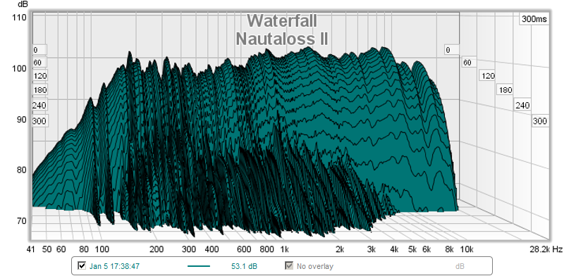
Waterfall (The initial 'mountain range' has a nice 'cliff' looks very nice - even and steep - I wonder if the secondary mid-range lower 'foothills' are due to the FC resonance?):
Spectral Decay (Spectrogram - less lobing the better?):
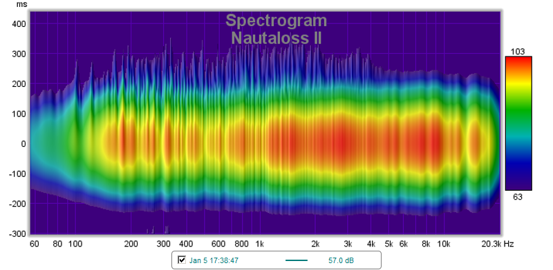
I am new to the last two plots so am not sure how to interpret them - but my guess is that they are good - excellent, I think. There has been no EQ'ing applied.
Please let me know what you think of the waterfall and spectrogram if you know how to read them and have examples for comparison.
I discovered the wonderful REW software which performs measurements that include waterfall and spectrograms. In case you have not seen REW, it is cross-platform (PC, OSX, and Linux) as it is written in Java and is available from here for free: REW - Room EQ Wizard Room Acoustics Software
I repeated my measurements with the UMM-6 mic and REW used the calibration file from the manufacturer of the microphone to provide measurements in actual dB SPL.
Here are the measurements again at 12 in from speaker with mic 39 in above floor, a home-built Texas Instruments TPA3116D2 amp (powered by 19 volt laptop SMPS), and PC is now a small HP Mini 110 netbook (which has a better sound card with less distortion than my previous laptop).
Frequency Response and Phase:
Harmonic Distortion:
Impulse Response (signal needs to be inverted next time...):
Group Delay:
Waterfall (The initial 'mountain range' has a nice 'cliff' looks very nice - even and steep - I wonder if the secondary mid-range lower 'foothills' are due to the FC resonance?):
Spectral Decay (Spectrogram - less lobing the better?):
I am new to the last two plots so am not sure how to interpret them - but my guess is that they are good - excellent, I think. There has been no EQ'ing applied.
Please let me know what you think of the waterfall and spectrogram if you know how to read them and have examples for comparison.
Attachments
-
 nautaloss-ii-meas-01-FR.png59.7 KB · Views: 17,842
 -
 nautaloss-ii-meas-01-thd.png81.9 KB · Views: 12,896
 -
 nautaloss-ii-meas-01-ir.png39.1 KB · Views: 2,724
 -
 nautaloss-ii-meas-01-gd.png47.4 KB · Views: 2,102
 -
 nautaloss-ii-meas-01-csd.png193 KB · Views: 2,217
 -
 nautaloss-ii-meas-01-spectrogram.png407.5 KB · Views: 12,471
Last edited:
Hi X,
I have been reading with interest in the sub and the Nautaloss I and II and will build something soon. My question is what would you use for rear and side surround HT speakers in the foam builds with the Vifa, a 0.4X Karlsonator mounted upside down on the ceiling or the Nautaloss I ? Or do you recommend them at all? I appreciate your answer.
Scott
Hi X,
I have been reading with interest in the sub and the Nautaloss I and II and will build something soon. My question is what would you use for rear and side surround HT speakers in the foam builds with the Vifa, a 0.4X Karlsonator mounted upside down on the ceiling or the Nautaloss I ? Or do you recommend them at all? I appreciate your answer.
Scott
Thanks for your interest Scott. When you say side, I assume you mean the 2 fronts in a 5.1 or the two sides in a 7.1 system? If I were doing it, I would use Nautiloss II on the main fronts and center front channel, Nautaloss I on everything else, and Nautaloss subs in two corners, preferably front corners. Alternatively, Nautiloss I for all channels except subs will work well too. A Karlsonator 0.4x can also be substituted for any channel and that will reduce dependence on sub.
If you want to skip a sub altogether, use Karlsonator 0.53x on two main fronts and Nautaloss I's everywhere else.
Hope that gives you some options.
Hi X,
Thanks for the reply. The Yamaha HT receiver I have can handle a 9.2 setup with 2 rears, 2 sides, Left, right, ctr and front ceiling mounted speakers for called "presence" speakers to bring the voice of the center channel to the middle of the tv. I like the thought of the Nautaloss I speakers for the ceiling. I did buy the Pioneer BoFu drivers a while ago to build the Nelson Pass TL for left and right fronts but not sure if they would integrate well with the speakers on the ceiling. Having 3 Nautaloss II's on a tv stand below the tv would look better with the subs in the corners. It's not a big room but would be a fun build for low a low price. I have to see if the foam core can be smoothed with filler and then painted with latex ceiling paint without peeling the paper. It's time to buy some #11 X-acto blades and get started. 🙂 Thanks, i'll post pics when building.
Scott
Be careful with water based paints as it will curl foam as it shrinks the paper on one side. It may warp your boxes. I would use latex paint to seal the exposed foam edges, then spray paint with non water based paint from a can. That way, the solvent doesn't touch foam and melt it. Test on plain piece before painting the real thing. Looking forward to your build. It should sound great. Were you going to use conventional cube BR subwoofer or build Nautaloss subs? Those are rather advanced projects and should be attempted after you have some experience making spirals, making braces, gluing and capping the final side. Do them last after you make several smaller Nautalosses.
Good luck.
X
Good luck.
X
Hi X,
I have built the 20" cornu spiral speakers and use modeling instant glues for foam so the building should not pose too much problem and I finished a set of the .4X Karlsonator. I am ordering the 6.5" woofers for the subs even though they are on back order with more Vifa drivers. I used to use polyurethane paint on my solid foam models and might try that on the foam board to see if it wants to lift or curl it will not react to the foam. I do have two cube subs but like the idea of building the subs. I will ask later how you wired up the push pull drivers when the time comes. I still don't understand how the sub works but have faith. lol Thanks!
Scott
Hi X,
I have built the 20" cornu spiral speakers and use modeling instant glues for foam so the building should not pose too much problem and I finished a set of the .4X Karlsonator. I am ordering the 6.5" woofers for the subs even though they are on back order with more Vifa drivers. I used to use polyurethane paint on my solid foam models and might try that on the foam board to see if it wants to lift or curl it will not react to the foam. I do have two cube subs but like the idea of building the subs. I will ask later how you wired up the push pull drivers when the time comes. I still don't understand how the sub works but have faith. lol Thanks!
Scott
Scott,
It sounds like you are well-seasoned to take on this project then. What brand of glue so you use - it sounds like Gorilla glue? Did you ever post photos of the 0.4x Karlsonator in the other thread? If not please do so as we would all like to see what they look like. The sub uses 4 drivers as you know, and I wired them in series/parallel to achieve the same nominal 4 ohms rating. The face to face drivers are in parallel with the one on the outside (where you see the basket) is wired in reverse polarity or out of phase electrically.) For convenience I wired the opposing drivers in parallel but it could probably be done the other way and not make a difference. Before screwing the drivers on I checked for correct polarity by applying +5v DC to the common speaker input for all 4 drivers and observed the direction of the cone movement. All 4 drivers should move in unison to push "out" of the enclosure. That is, the 2 mounted outside should move backwards towards the magnet and the internal drivers should move away from the magnet. If you do it wrong not to worry, you will know right away as there will be no sound. I also put a small amount of polyfill stuffing in between the spaces of the two opposing drivers. You will also need a spacer ring made of foam core between the two drivers to allow the rubber surrounds to move freely and not touch each other.
I did some real time spectrum measurements of the sound (music program rather than sine sweep) with the sub pointed into a corner with a layer of 2 in thick open cell foam in the area immediately surround the wall opposite the drivers. It acts as a natural low pass filter and I saw bass as low as 30 to 40 Hz and a roll off from 200 Hz on.
Hi X,
If you remember I built the 0.4X Karlsonator the same day you did and have since built the second one with the extra foam in the places you specified and I will post more pics on that thread. I use cyanoacrylate (Ca) instant glue that is foam safe and just ordered some different instant glue that has a medium cure time that is cheap but strong. See the links below.
Evotite CA460 Foam Safe Super Glue (Medium)
Clear Foam Glue (Medium Cure) - Large 100ml
I have not tried Gorilla glue yet because the instant stuff is so quick but might try some on the joints that I don't have to hold.
I did notice the foam you had on the wall corner in your picture and thought that was for reflections and I can put both subs in the corners on either side of the tv. You mentioned that you use a small amount off polyfill between the cone faces, is that to tame the higher frequencies from the driver?
Thanks,
Scott
Scott,
Sorry I forgot that you were the one who built the 0.4x on same day as me! 🙂
I never thought of using cyanoacrylate glue - aka super glue. It does indeed dry fast but does it bond paper surfaces? You must be using formulation that is viscous and designed for paper/foam. Isn't that stuff kind of pricey?
Anyhow, so glad you are on-board with the Nautaloss build for a HT. I am realizing that I have enough speakers now to set up a HT system but have no receiver yet. Yes, my idea was that adding some polyfill in between the drivers will help to reduce high frequencies, but more to damp out those oscillations that were so problematic with the single driver. It probably doesn't do much. It also adds a tiny bit of mass to the moving volume and that may reduce fs somewhat.
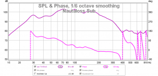
Measurements of Nautaloss Sub, Corner-Loaded
Placing the Nautaloss sub in a corner with some open cell foam seemed to make it perform so much better than a direct radiator speaker that I decided to make some new measurements with the REW software. My two reasons for using the corner loading was that I only had a single sub and needed more SPL efficiency to fill the room, and I wanted to reduce the HF's coming through since I am running full range for now.
The measurements indeed do reveal that the speaker performs substantially better in the bass extension department and a very effective low pass filtering was performed by the reflection off the corner which has open cell foam adjacent to where the drivers are. The most surprising aspect of this arrangement was that even running full range, the corner placement provided a natural acoustic crossover that almost matches exactly what I needed - roll off from 200 hz and above to integrate well with the Nautaloss tops.
The measurements were made with the UMM-6 mic at driver level (about 12 in from the floor) and at a distance of 1 m in reflected path from the driver radiator surfaces. The amp is a Yamaha RX360 45 watt/ch receiver running in mono (single channel) at about 11 o'clock volume dial with tone controls set at max bass and min treble adjustment. This is my usual listening volume setting which produces about 85 dB at the listening position.
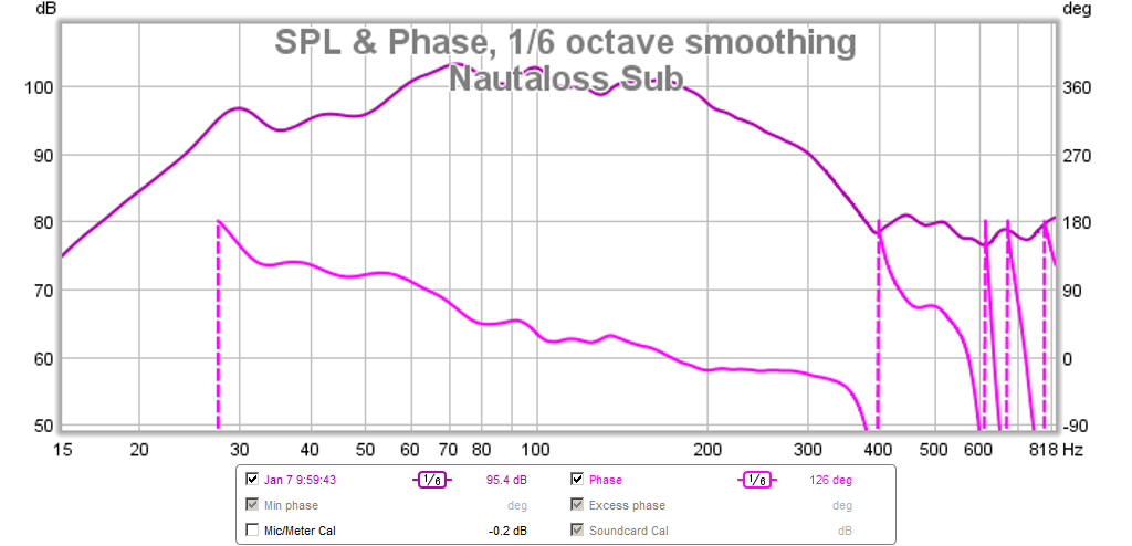
SPL vs Frequency - here we can see that the bass extension reaches down into 30 Hz - probably room enhanced for sure, the phase doesn't wrap as it varies almost linearly over 120 deg from 200 Hz down to 50 Hz. The main +/- 3dB bandwidth is 52 Hz to 200 Hz, but there is now the -6 dB reach is at 26 Hz!
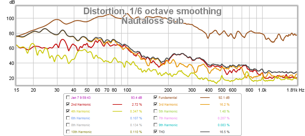
The THD varies from about -50dB at 200 Hz and goes down to -20 dB at 40 Hz, with the worst spot being -11 dB at 33 Hz. In general though, the performance above 40 Hz is satisfactory for such a budget driver that doesn't have shorting rings, or other premium features to reduce THD.
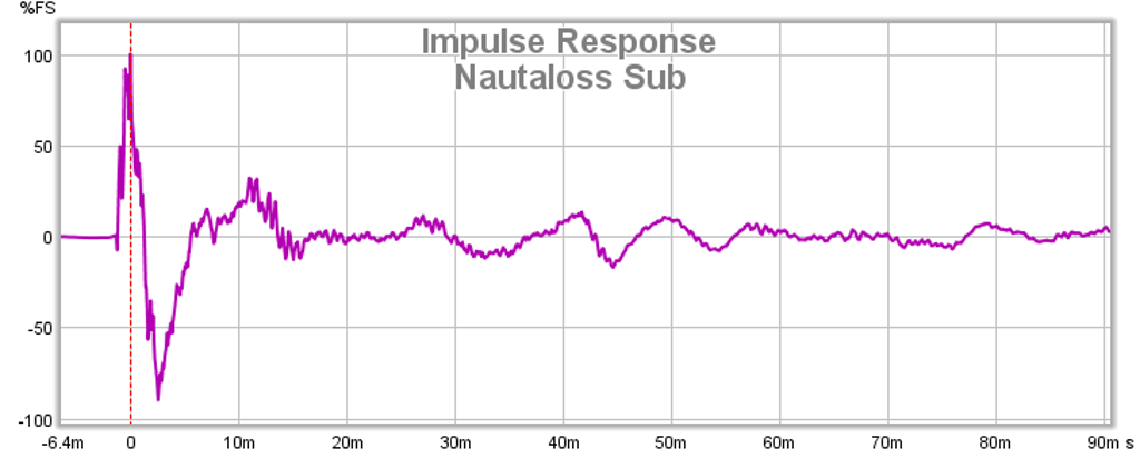
The Impulse Response looks excellent and confirms my subjective assessment that the bass is tight and articulate - notice the main sharp peak followed by a single negative peak with subsequent bounces of much reduced amplitude. I think that this is a major outcome of this speaker design.
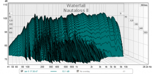
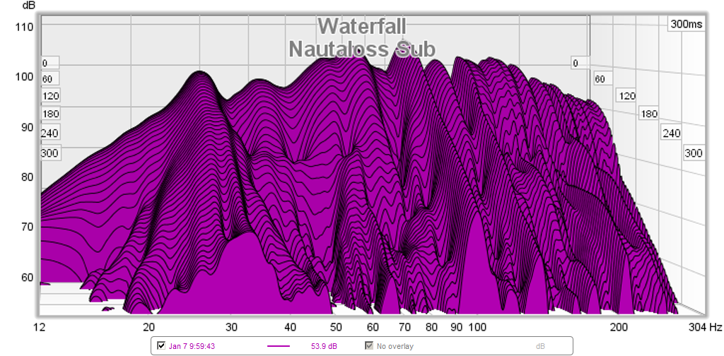
The Waterfall plot does show that this speaker is not as clean as the Nautloss II tops. However, I wonder how much of this is simply room mode contributions? Perhaps waterfall plot experts can chime in here with their assessments/opinions?
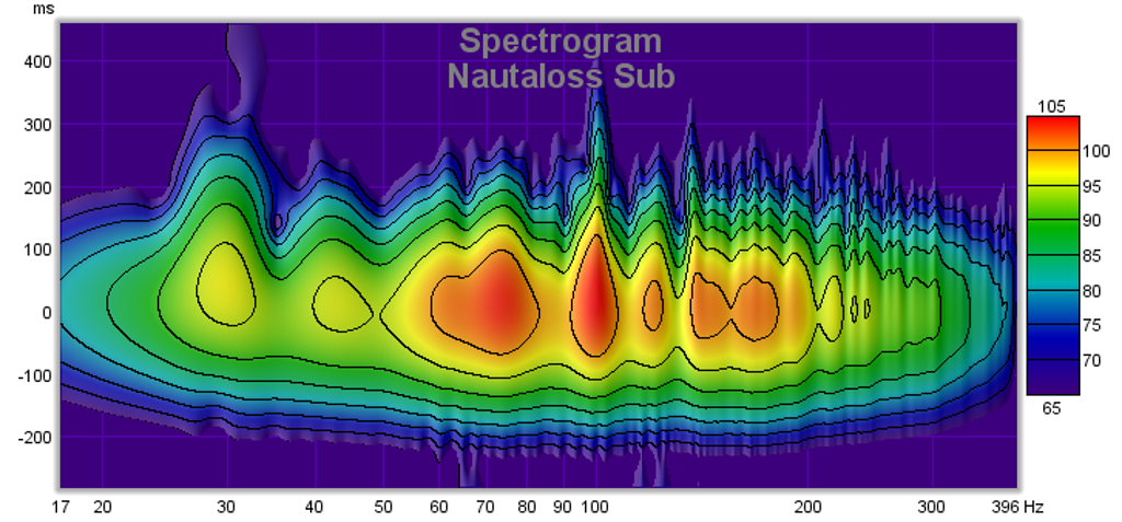
The Spectrogram reveals the same info as the Waterfall plot but in a color contour format. Obviously there are bumps, lobes, and tendrils all over this mountain range and it is not ideal looking like the loaf of bread that the Nautaloss II was. What can be done to improve this performance? How much of this is foam core cabinet resonance?
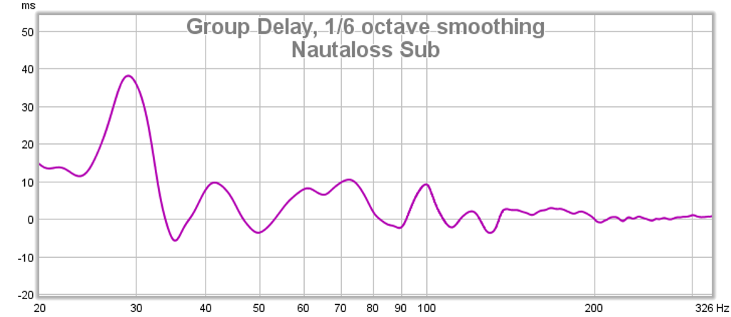
Finally, the Group Delay shows reasonable performance (+/- 5 ms) from 200 Hz down to 35 Hz, below which it starts to climb to unacceptable levels.
There it is, the Nautaloss sub woofer fully-measured for your pleasure...
Not so perfect this time so maybe more discussions can ensue 🙂
Placing the Nautaloss sub in a corner with some open cell foam seemed to make it perform so much better than a direct radiator speaker that I decided to make some new measurements with the REW software. My two reasons for using the corner loading was that I only had a single sub and needed more SPL efficiency to fill the room, and I wanted to reduce the HF's coming through since I am running full range for now.
The measurements indeed do reveal that the speaker performs substantially better in the bass extension department and a very effective low pass filtering was performed by the reflection off the corner which has open cell foam adjacent to where the drivers are. The most surprising aspect of this arrangement was that even running full range, the corner placement provided a natural acoustic crossover that almost matches exactly what I needed - roll off from 200 hz and above to integrate well with the Nautaloss tops.
The measurements were made with the UMM-6 mic at driver level (about 12 in from the floor) and at a distance of 1 m in reflected path from the driver radiator surfaces. The amp is a Yamaha RX360 45 watt/ch receiver running in mono (single channel) at about 11 o'clock volume dial with tone controls set at max bass and min treble adjustment. This is my usual listening volume setting which produces about 85 dB at the listening position.
SPL vs Frequency - here we can see that the bass extension reaches down into 30 Hz - probably room enhanced for sure, the phase doesn't wrap as it varies almost linearly over 120 deg from 200 Hz down to 50 Hz. The main +/- 3dB bandwidth is 52 Hz to 200 Hz, but there is now the -6 dB reach is at 26 Hz!
The THD varies from about -50dB at 200 Hz and goes down to -20 dB at 40 Hz, with the worst spot being -11 dB at 33 Hz. In general though, the performance above 40 Hz is satisfactory for such a budget driver that doesn't have shorting rings, or other premium features to reduce THD.
The Impulse Response looks excellent and confirms my subjective assessment that the bass is tight and articulate - notice the main sharp peak followed by a single negative peak with subsequent bounces of much reduced amplitude. I think that this is a major outcome of this speaker design.
The Waterfall plot does show that this speaker is not as clean as the Nautloss II tops. However, I wonder how much of this is simply room mode contributions? Perhaps waterfall plot experts can chime in here with their assessments/opinions?
The Spectrogram reveals the same info as the Waterfall plot but in a color contour format. Obviously there are bumps, lobes, and tendrils all over this mountain range and it is not ideal looking like the loaf of bread that the Nautaloss II was. What can be done to improve this performance? How much of this is foam core cabinet resonance?
Finally, the Group Delay shows reasonable performance (+/- 5 ms) from 200 Hz down to 35 Hz, below which it starts to climb to unacceptable levels.
There it is, the Nautaloss sub woofer fully-measured for your pleasure...
Not so perfect this time so maybe more discussions can ensue 🙂
Attachments
-
 nautaloss-sub-spectrogram-01.png593.6 KB · Views: 1,316
 -
 nautaloss-sub-waterfall-01.png364.6 KB · Views: 1,317
 -
 nautaloss-sub-ir-01.png63.9 KB · Views: 1,314
 -
 nautaloss-sub-thd-01.png130.7 KB · Views: 1,315
 -
 nautaloss-sub-spl-01.png86 KB · Views: 1,313
 -
 nautaloss-sub-gd-01.png61.1 KB · Views: 1,241
Last edited:
Scott,
Sorry I forgot that you were the one who built the 0.4x on same day as me! 🙂
I never thought of using cyanoacrylate glue - aka super glue. It does indeed dry fast but does it bond paper surfaces? You must be using formulation that is viscous and designed for paper/foam. Isn't that stuff kind of pricey?
Anyhow, so glad you are on-board with the Nautaloss build for a HT. I am realizing that I have enough speakers now to set up a HT system but have no receiver yet. Yes, my idea was that adding some polyfill in between the drivers will help to reduce high frequencies, but more to damp out those oscillations that were so problematic with the single driver. It probably doesn't do much. It also adds a tiny bit of mass to the moving volume and that may reduce fs somewhat.
Hi X,
Yes the glue is expensive compared to the speakers we build out of foam, but compared to a model airplane it isn't. 🙂 The glue I used on the Cornu and the Karlsonator is $12 an oz., but the new glue is $5 for 3/4 an oz. It was scary on the Cornu when running a bead on all the walls and in one motion to line the back wall up with the channels and join them, pile the weight on, there is no going back. This glue is desigend for porus materials and is thicker and will stay on the surface wet until you join. It works great on paper and will not melt the foam. As soon as the glue arrives I will start building the Nautaloss I. I might try a technique I used in building an airfoil wing using the Dollar tree foamboard. I cut the shape of the piece I need to curve, rub alcohol on the paper to soak through the paper until the glue releases, peel the paper off (both sides), spray the paper and foam with 3m77 contact adhesive, curve the part then apply the paper back, it holds the shape when the paper adheres, kind of a pain to do but if I make a foam jig to hold the shape of the spiral it might be easier when making more than a few.
Thanks,
Scott
Peeling the paper off and reglue in curved shape with 3M fast tack - cool technique that works on simple curves like an airfoil but I don't see how you do it on a multi revolution spiral curve? Have you tried the scoring the concave sides and hot glue method?
I will have to try your technique sometime.
As for using cyanoacrylate for capping final side - that is scary (and expensive). Give PVA white glue and weights to clamp a try - works very well and I have had good success. I have a trick and that is to use several hot melt tack points internally in addition to the pva. This way I have 20 seconds to adjust the alignment and make sure edges line up before hot melt sets. Then the alignment is preserved while the weights do their job of ensuring the PVA dries in a tight seal.
For grins I turned the volume up to 1 o'clock position and ran the freq sweep. The mic registered 110 dB at 1m and the speaker literally moved 3 inches after the sweep was done! 😀 I had no idea this thing could get this loud with a 45 watt amp. The sound output did not appear to be clipped or otherwise compromised with xmax limits.
Hi X,
On the first Cornu I scored the paper but used instant glue. The tighter the curve the shorter the piece so it was managable. I didn't try the hot melt, though I might try it in the future. I will give the jig a try and let you know how well it works. It might be worth the hastle when making six speakers.
I like your method of using PVA and hot melt and I was thinking the same to reduce the cost of the instant glue. I could put a drop every three inches and use either PVA or a cheaper foam glue.
I will try to get two Nautaloss I speakers done within the next few days to give a listen and I will take pics. 🙂
Thanks,
Scott
I like your method of using PVA and hot melt and I was thinking the same to reduce the cost of the instant glue. I could put a drop every three inches and use either PVA or a cheaper foam glue.
Another trick: Glue a small tab of FC on the inside edge of a wall where you want to use hot melt to tack the top panel on. The tab will be a small 1 in square that hangs out 90 deg from main wall or channel. The tab gives you room to apply a large dab of hot melt glue so that it has more thermal mass and sets slowly giving you time to apply more hot melt to all the other tabs prior to putting the final panel on. Additionally, it gives you a few more seconds to actually slide the panel around to ensure the perimeter is flush and well aligned. Also, the edge has a seamless PVA bead and you don't have wet PVA touching the hot melt.
I got some feedback in multiway forum on how to read and perform spectral decay measurements. I have to get measurements at 4 inches away to keep it at about 3 ms away from speaker to reduce room influence. Decays in 1sec and below are room effects. So my sub measurements above mostly show energy storage and decay in the room environment.

Juhazi tipped me off on this very nice write up of speaker measurement and what a 'good' speakers' measurement looks like here:
Measuring Loudspeakers, Part Two | Stereophile.com
CSD's of a driver should be in single ms range. Time to redo measurements 4 inches away and I will see if I can time gate the measurement.
Measuring Loudspeakers, Part Two | Stereophile.com
CSD's of a driver should be in single ms range. Time to redo measurements 4 inches away and I will see if I can time gate the measurement.
- Home
- Loudspeakers
- Full Range
- The Nautaloss Ref Monitor