Andrew, we are talking about AC theory/stability, not linearity. In any case, the amplifier might be defective without the capacitors.
Artu, I have seen this in my simulations too and the solution I found was either the same or similar. I explained it by thinking that the amp+compensation has an effective inductance, and this coupled with the capacitance of the output devices becomes a resonator. Therefore a C or RC placed in the right place in the circuit would dampen the resonance.
Still, OS's simulations and mine don't show nearly such a severe resonance. What have you done? Did you put a capacitor in series with the load?
Also, I don't think the AC analysis for LTSpice and NgSpice are any different. They solve a linear function for the circuit, disregarding anything nonlinear. So you might say the AC analysis is the normalized response of your circuit with an infinitesimal input signal.
I have been considering switching to NgSpice because it is a native Linux simulator, and I switched to linux earlier this year. I also suspect it is higher quality and has better features because it is open-source. Unfortunately there is no simple schematic/netlist function like for LTSpice, and this is what makes LTSpice such a great simulator.
- keantoken
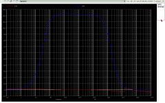
OLG bandwith
Hi AndrewT In short, it doesn't strangle OLG, Plots showed are with input LPF, and output loaded.
1) OLG without dampers
2) OLG with dumpers
You will see a little displacement of the 2nd zero.
Cheers
Arturo
PS all simms showed are from my amp, I haven't simmed OS amp yet.
Hi AndrewT In short, it doesn't strangle OLG, Plots showed are with input LPF, and output loaded.
1) OLG without dampers
2) OLG with dumpers
You will see a little displacement of the 2nd zero.
Cheers
Arturo
PS all simms showed are from my amp, I haven't simmed OS amp yet.
Attachments

"Artu, I have seen this in my simulations too and the solution I found was either the same or similar. I explained it by thinking that the amp+compensation has an effective inductance, and this coupled with the capacitance of the output devices becomes a resonator. Therefore a C or RC placed in the right place in the circuit would dampen the resonance."
I agree Keantoken, and at much higher frequencies the 'magic' multiplies, that why I always prefer to design an analyse the thing a a whole, it is not simple gathering the best input, the best VAS or buffer+output together, because that way you could fall in a risky bet.
With LTSPICE you have the great advantage of the graphical front end, but I believe that much SPICER's doesn't know in deep SPICE itself. SPICE has a language interpreter that allow you to simulate (and do things, running your own programs), that I believe many users of LTSPICE don't do or doesn't know how to do it. To arrive this point, before even choosing the final topology and component values, I've did some analysis aided by other programs to get a more general insight to prove if my concept would be worth or not. Then I simmed (with SPICE) in a more limited context knowing on where I did want to arrive, changing bias point, choosing active devices linear regions, values ... cut and try.
Finally beware that spice runs a model (your amp) but there are several little details that may appear in the real world (stray components), so it is wise to have room to tune it without sacrificing the "goods"
Cheers
Arturo
Ahh C9, C10 ... very important, Os you are close ... indeed they do rolloff HF,but the mechanics is little bit more complex, I will try to explain succinct.
The VAS is differential to some extent (at audio BW, and additionally enhances THD), but at high (critical) freq. changes it's behaviour. Each leg has its own 'natural' freq (far above audio) s1 (C9,C10) and s2 (VAS driver with Cdom) where s1 < s2, and are emitter coupled (both 'competing' with very low impedance). To show it with a simple analogy, it is like Formula 1 suspension system, to coaxial springs each on with it's own natural frequency one interferes (dumps) the HF oscillations of the other. Another benefit is despite that the common collector has much low Miller parametric FB capacitor (than a common emitter), it helps to the stability of this leg. With this arrangement you can use less degeneration at input (> OLG, better THD trough BW) and also reduce the 'brute force' BW limiting Cdom. To exploit this feature optimally you should strip out the degeneration of the VAS (tying both emitters directly). Another source of stability (and less noise) in my design is the super low FB loop, at the cost of offset as you correctly pointed. An additional warning is that even a AC decoupled loop scheme, the sims does not take account thermal imbalance which indeed could produce a significant offset.
Cheers
Arturo
BTW this VAS is mine, maybe others discovered before me, but I haven't seen in the literature.
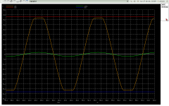
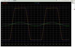
Hi, artu. I never intended to build exactly Your amp ... but there are features (the VAS) that I like. At this site/ link: --- A HiFi Power Amp --- , there is a very similar one. I noticed with a VERY SMALL LTP degeneration your original compensation works as described. My goals were to better the Leach while using similar compensation. My transient tests confirm that with lower loop gain (47R Re) the "backside" compensation (the 270-390p - C9/10) creates much overshoot (pix 1 -with c9/10)which corresponds to the phase margin plots in my last post. Removing c9/10, gives me this (Pix 2 - without C9/10). "Littlefish" seems to have gotten nearly the same results , mine are a little better as I use better devices .... MJE340/50 are so "yesterday" 😀. Clipping at my max 350 watts + (144v p-p) is a breeze for this amp , better than any "blameless" , nice rounded edges .. almost "soft" clipping (PIX 3)... NICE. 😎
Worst case , I won't be out of luck. I intend on keeping the pads for the extra comp. there , I might want to experiment with lower impedance NFB networks , etc.
OS
Attachments
My question is why SPICE doesn't have thermal simulation yet. Does NgSpice simulate thermals without "help"? Thermals are just as important as everything else, IMO...
- keantoken
- keantoken
My question is why SPICE doesn't have thermal simulation yet. Does NgSpice simulate thermals without "help"? Thermals are just as important as everything else, IMO...
- keantoken
here's my "thermal simulation" 😀
An externally hosted image should be here but it was not working when we last tested it.
OS
BTW this VAS is mine, maybe others discovered before me, but I haven't seen in the literature.
I did use a differential vas in a symetrical design many , many
years ago, and the idea was already very old..
Nothing was invented after 1980....
clipping issue
The clipping behaviour of mine. Question did you stripped the degeneration resistors of the VAS? if not so the circuit is working in a different way I've intended in design.
1) start clipping (before input saturation)
2) clipping (input saturated)
3) hard clipping
Note that when medium to hard clipping there are very little overshoots at the edges due to the stored charge at output BJT cannot be ideally handled by my buffer, but it is a quite decent response.
Anyway to discard a possible instability is always good stimulate the amp with a very very high square wave (not clipping it, but just before).
Cheers
Arturo
Attachments

... here's my "thermal simulation" ...
Very good I used also ... try to point only one of the CLPT inputs ha ha
Cheers
Arturo
Very good I used also ... try to point only one of the CLPT inputs ha ha
Cheers
Arturo
Hi Keantoken, SPICE indeed to thermal simulations with the parameters TNOM (nominal temp for the models parameters) and TEMP (for the actual silicon ... temp.). But it is difficult to simulate imbalances ...
Cheers
Arturo
Cheers
Arturo
"Did you put a capacitor in series with the load?"
Hi Keantoken, I've didn't answer that, no absolutely ...
Hi Keantoken, I've didn't answer that, no absolutely ...
Question did you stripped the degeneration resistors of the VAS? if not so the circuit is working in a different way I've intended in design.
No degeneration in the vas, at least between the emitters,
since they are not needed, but surely, heavy degeneration
in the input differentials to improve stability behaviour.
Artu, what is needed is a computation of junction temperature at every step of the simulation, in realtime. To my knowledge no simulator does this. Such a simulator would allow modeling of the thermal characteristics of the die, case and heatsink. It doesn't seem by your description that NgSpice does this. LTSpice is the same. Global temperature and junction temperature as constant values, but no actual thermal simulation.
- keantoken
- keantoken
Hi Wahab, at lower FB loop this effect (the clipping overshot) should be better, or maybe the output impedance of the input stage is a little high ?? i am guessing (as didn't simulate OS amp. yet). Anyway values from one circuit usually don't work good in another, a amp is a chain of dependencies even much more if it has feedback.
Cheers
Arturo
Cheers
Arturo
About SPICE and TEMPERATURE
Keantoken, no, SPICE does models TEMPERATURE as I pointed with the TEMP global parameter, even you can sweep temperatures with DTEMP, but requires in deep SPICING
example:
.options itl1=500 itl4=100 acct list node opts abstol=1e-10 reltol=0.001 gmin=1e-18 method=gear tnom=27 temp=65
here tnom is the NOMINAL temp at where parameters where measured (extracted) from the DUT.
and TEMP is the actual temperature of silicon resistors ....
Cheers
Arturo
Attachments
Well yes, it can simulate at different constant temperatures, but it can't simulate transistor self-heating, which is what I'm talking about. It can't simulate temperature changes on the fly.
- keantoken
- keantoken
Hi Wahab, at lower FB loop this effect (the clipping overshot) should be better, or maybe the output impedance of the input stage is a little high ?? i am guessing (as didn't simulate OS amp. yet). Anyway values from one circuit usually don't work good in another, a amp is a chain of dependencies even much more if it has feedback.
Cheers
Arturo
Hi Arturo
Frankly, i didn t explore the clipping behaviour deeply since
the results i got were good enough, though it s to be credited
to the circuit, not to me....
The input stage output impedance is vaguely set with the collectors
resistors that will also be the discharge path of the saturated VAS
base stored charges.
Generaly, a value under 3K is fairly enough, though high speed variants
will reduce it in the 0.5K/1K range.
Indeed, the problem is even more solved by the symetricality of the vas
as the saturated half output will be brought out of its state by brute
force conduction of the other half of the vas, and in that respect,
this is a major advantage compared to the ubiquitous single ended
vas that are the by products of the blameless like ubiquity....
cheers
Artu, what is needed is a computation of junction temperature at every step of the simulation, in realtime. To my knowledge no simulator does this. Such a simulator would allow modeling of the thermal characteristics of the die, case and heatsink. It doesn't seem by your description that NgSpice does this. LTSpice is the same. Global temperature and junction temperature as constant values, but no actual thermal simulation.
- keantoken
What I would like to do is just step simulate from 15C to 60C the 4 IPS trannies to see the temp coefficient vs. gain differences between P/N channels , or to plot the offset /THD with these variables. I have read that to just degenerate the 2 sides independently (example- Re 40R for P and 47R for N) will minimize any offset or large signal non-linearities. Worst case I can use the CRO/DMM with the hairdryer on the real thing
 .
.OS
Keantoken, yes you are right, that's a limitation as you said, I believe this kind of realism will never be implemented in SPICE (too complex), but what is more important is that in reality components are not clones (even I managed to tweak slightly two versions of the same model to mess symmetry). So this issue is to be always verified in the real world.
Cheers
Arturo
Cheers
Arturo
Hi Wahab, completely agree, that's a property of the symmetrical VAS, but dynamic stability at high freq. is another issue in general (even it can be easily modelled with two port S,Y,Z parameters for any device regardless the topology) which is what I am arguing, it is what I am trying to understand, (it is very complex).
Cheers
Arturo
Cheers
Arturo
- Home
- Amplifiers
- Solid State
- The MONGREL (supersym II)