Single npn servo
Here it is:
Hope this explains it.... For 11.7mA through R14 with 70V rails, you are looking at 4K7 2W (645mW dissipation).
These values place around 140mW dissipation in the half watt 15V zener, which is lineball for long life.
Hugh
Here it is:
Hope this explains it.... For 11.7mA through R14 with 70V rails, you are looking at 4K7 2W (645mW dissipation).
These values place around 140mW dissipation in the half watt 15V zener, which is lineball for long life.
Hugh
Attachments
Last edited:
Here it is:
Hope this explains it.... For 11.7mA through R14 with 70V rails, you are looking at 4K7 2W (645mW dissipation).
Hugh
A single device ACTIVE servo ... nice !! I really appreciate that. have you actually used it ? I will "plug it in" to LT. 🙂 😎 a pix is worth a 1000 words.
I want to honour 😀 poor prof. Leach with a very good simple voltage board AND triple OPS.
OS
Yes, this circuit features on my NAKSA 100, and controls offset very well in the face of some fairly strong thermal drift.
Like you, I prefer not to use ICS because they require a bipolar power supply, and this is tricky to lay out on a wide pcb.
Hugh
Like you, I prefer not to use ICS because they require a bipolar power supply, and this is tricky to lay out on a wide pcb.
Hugh
And I must add that adjusting only one leg will have 1/2 resolution. Anyway any long term offset below 10 mV doesn't harm.
I'm "spoiled" ... I like my precision <1mV setups.
OS
Anything finer than 10mV control is a complete waste of time. I can promise you Pete that there is absolutely no freakin' difference in the sound quality.....
Hugh
Hugh
Yes, this circuit features on my NAKSA 100, and controls offset very well in the face of some fairly strong thermal drift.
Like you, I prefer not to use ICS because they require a bipolar power supply, and this is tricky to lay out on a wide pcb.
Hugh
I will keep my IC's (ICS ?? ) separate. They are best for preamps, buffers for headphone amps (I like Bonsai's diamond buffer discrete/IC combo). A good discrete amp should be ALL discrete. All my amps are AT LEAST as good as some OP-amps in the offset/noise/slew category.
Thanks again for that offset diagram. Here is my "secret"...
I have figured out the TMC/bootstrap method. Just take your TMC feedback from the bootstrap feedback point (between the 2 resistors), not the output. Up {Rtmc} to 820/1k ... all is well (stable , bye bye Xover distortion) GREAT sound (am listening now).
OS
Last edited:
Anything finer than 10mV control is a complete waste of time. I can promise you Pete that there is absolutely no freakin' difference in the sound quality.....
Hugh
Just a perfectionist , If you can , why not. Long term , if your offsets are so low , any drift with age should also be lower. On the AX , I had to pick a gross "mismatch" to get over 10mv. If I then trimmed to compensate with "offset adj." , one device would be degenerated with a 70R and the other with a 85+ R. With a better match (the ones I am listening to now) I ended up with 2mV initially .. 1/4 turn of the trimmer - .5mv and under. checked the static LTP Re's , one was 82.5R , the other was 82.8R .. way better .. at least electrically. I agree , these amps sound so good "out of the box" that these small errata's are most likely inaudible , but why not correct them ???
OS
Last edited:
Pete,
I have done the servo again for more current control, since the LED current range required to give a decent variation of the CCS output could be quite a bit more than I'd designed for. Accordingly, an updated version is attached, with much more range.
Perfection is great, but of course you also have to balance it against complexity and cost. I gun for <10mV these days.
Cheers,
Hugh
Attachments
Hugh just a little question, the behaviour of the servo when clipping?
Well I am not biased against IC's and not so convinced about PCB area issue, also you can do a +/-15V form the +/- power rails with a couple of zeners/resistors, the beauty of IC's is the high CMRR that makes them virtually immune to the power ripple. High end amp also needs FAST speaker protection (a crowbar ...= additionally PCB & circuitry).
So, why not go Mercedes Benz ???
Hi Arturo,
Ah, clipping, always a tricky one!
If positive clip is longer than one time constant, which here is 2.2s (and indicates a LATCH, a serious condition) then base steadily voltage rises to 63% of rail, very quickly passing more current through the transistor and quickly chopping out current in the LED. At +0V6 on the LED, the zener goes into conventional conduction, limited by the 2K2 resistor, but a steadily rising current which won't do much damage. But, a rising voltage across the LED at about 5V will likely destroy it, so a 4148 diode in series with this LED would be a great idea. As for the CCS, it will start to generate high currents as the LED voltage reference is pulling high current.
If the amp clips negative, it will pull the servo device base down, carrying the emitter with it whilst current still flows. When servo emitter drops below -2V, the device will stop conducting, and no current will be pulled through the CCS reference LED. The CCS will then switch off.
Yes, things are not wonderful, Arturo, BUT, if the amp is clipping to this extent (holding rail voltage for more than half a second or so) it will be latching which indicates severe design issues in the amp.
Possibly more work needs to be done here, and an IC servo might be better behaved in these situations. We could limit the range of input to the servo base with diodes, that might be useful......
Cheers,
Hugh
Clipping ... 😀 , Just avoid it. If I ever clipped on 75V rails , I'm sure my speakers would be toast well before the fact. I do my initial tests on my 45V rail rig , so I will clip this one as I do for them all. (for real !!) if it blows , I learn more. 😀 I know that sounds primitive , but I have shorted , oscillated and regularly abuse the mongrels in every way (sometimes on purpose) ... very resilient circuits.
OS
OS
yes, trimming R44, or R20 sets output offset if you don't adopt DC servo.Just 1 or both of the LX1.0 CCS's , if made adjustable , will make for a dandy offset adjust.
And definitely disconnect ground from the two R21, R33 resistors. Maybe add a LED to monitor current
Last edited:
Hi AndrewT, yes you can trim DC offset at certain temp below 1mV. but it will be not long term stable as temperature changes (winter - summer), so this topology NEEDS A SERVO as there are two input amplifiers that aren't clones (each has its own temp. profile), and in extreme conditions could drift as high as 1V !!!
I think you are wrong..it will be not long term stable as temperature changes (winter - summer), so this topology NEEDS A SERVO as there are two input amplifiers that aren't clones (each has its own temp. profile), and in extreme conditions could drift as high as 1V !!!
The two matched pairs in the complementary LTPs run at the same temperature since they have the same current and the same voltage.
If you thermally couple the LTP pairs then you find that output offset is low and you find that offset drift is low.
It is preposterous to suggest that a 1mV offset could rise to 1000mV offset due to operational temperatures.
I know - just make the time constant larger than the amp can reproduce. IE the input is overloaded before the amp can clip with such low bass.
BTW, I'm trying to implement rudimentary thermal simulation in LTSpice. Guess what? you get convergence errors if your circuit has thermal runaway.
Distortion profile changes a lot too. But I would have known this if I had just done the math (Remember, lazy people work 3 times harder). Most of it is increased 2nd harmonics from the VAS. In this case the feedback transistor also contributes, because the test amp has no gain and it sees the full voltage/power/dissipation swing of the output.
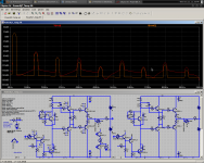
So there it is. Thermal distortion DOES INDEED EXIST.
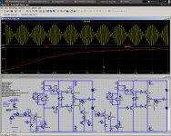
First plot is the FFT with/without thermal simulation (Red/Orange). Second is the heatsink temperature (red) and junction temperature of the Vbe multiplier (orange) at 50Hz+55Hz. Heatsink is 2C/W.
- keantoken
BTW, I'm trying to implement rudimentary thermal simulation in LTSpice. Guess what? you get convergence errors if your circuit has thermal runaway.
Distortion profile changes a lot too. But I would have known this if I had just done the math (Remember, lazy people work 3 times harder). Most of it is increased 2nd harmonics from the VAS. In this case the feedback transistor also contributes, because the test amp has no gain and it sees the full voltage/power/dissipation swing of the output.
So there it is. Thermal distortion DOES INDEED EXIST.
First plot is the FFT with/without thermal simulation (Red/Orange). Second is the heatsink temperature (red) and junction temperature of the Vbe multiplier (orange) at 50Hz+55Hz. Heatsink is 2C/W.
- keantoken
Attachments
WRONG ???
AndrewT I am NOT WRONG, thinking that CLTP are perfect (even if thermal matched) is naive, I have LOT's of time investigating, studying thermal this issues on CLTP inputs, even in a perfect thermal coupling (all over the circuit) that spans 60°C the drift is 0.6V. For a real device this could be twice, so it is not unreal to have 0.5V over 30°C (depending also heavily on how subsequent stages perform), thermal and electric matching is never perfect. Even more, a circuit may have a positive thermal behaviour (it amplifies thermal imbalance) which are prone to thermal runaway or a negative thermal behaviour which prevents this situation, my designs take care of this issue. There are several techniques to achieve this, some related to the BUFFER+OUTPUT, others at input (what we pointing here), see Hawksford papers ...
Cheers
Arturo
- Home
- Amplifiers
- Solid State
- The MONGREL (supersym II)