how did X2 appear in the link?
The datasheet makes no mention of X2 rating and goes on to state <=250Vac rating. This is not X2.
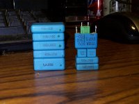
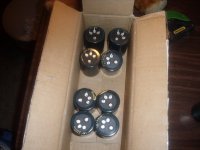
Neither of the pics shows an X2 rating on any of the caps.
where does it claim snubber duty?Those are snubber capacitors! No way those could be good coupling caps, right!? haha lol
On the contrary, design for high-frequency pulse operation at hundreds of volts should make these caps excellent.
With a maximum of 200V/us these can be bettered by many others for good pulse operation.
Last edited:
OS, I just switched in one of those 5n6 snubbers for compensation in my headphone amp, it sounds much cleaner and natural, with a better soundstage. This is a change I'd definitely recommend.
The type used is a Rifa Evox PFR, non-metallized polypropylene film.
http://www.kemet.com/kemet/web/homepage/kechome.nsf/file/General%20Information%20-%20Pulse%20Capacitors/$file/F9000_GenInfo_PulseCaps.pdf
- keantoken
The type used is a Rifa Evox PFR, non-metallized polypropylene film.
http://www.kemet.com/kemet/web/homepage/kechome.nsf/file/General%20Information%20-%20Pulse%20Capacitors/$file/F9000_GenInfo_PulseCaps.pdf
- keantoken
Last edited:
those PFR pulse caps are the only film foil caps in that range. Equivalent to MFP
I note the last construction is similar to Wima's version of film foil. It too has part foil and part metallised film.
I note the last construction is similar to Wima's version of film foil. It too has part foil and part metallised film.
Some advice please.
I've looking at a 6/12 output Mongrel so looking at the easy ways to do this, we have both OS's and Alex MM PB250 to look at.
One question on Alex's design, there looksto be no diodes between the rails and NFB (D98, D99 from OS's PB250) and the 22uf caps have been added what affect would these two changes have?
Is there any benefit in adding these caps to OS's design?
Alex would you be OK if I take your board layout as a starting point for a 6/12 output version and post the layout?
Thanks
Rob
Hey , rob ... The PB250 is VERY good , I was running 2 pair 😱 8R loudspeakers ALL day at very high SPL without the board even breaking a "sweat" . With a 600VA trafo and 70-0-70VDC supply the dynamic range of this amp is breathtaking , even scary !! The D98/99 are flyback protection diodes for the OPS. I fried one of them when I killed my left channel , it saved a few trannies before it went.
Adding those little 22uF caps near the OP devices would have very little effect in relation to the big 4700uF devices on the 12mm thick power rail traces of the PB250.
Keen , (below) is a preview of the NEW PB60 board you will get with the 2 AX's I will mail you. For me I also "remodeled" the AX (BELOW 2) ... same circuit , better layout , ALL mongrel boards are now 102 X 87 mm (3 1/2" X 4") with room for VERY large input caps. I am making the Mouser order now for 6 PB60's and my new PS100 CLC power supply .. I need a recap badly.. (below3).
OS
Attachments
Which is what nominal secondary voltage in your universe...?With a 600VA trafo and 70-0-70VDC supply...
OS
Which is what nominal secondary voltage in your universe...?
"in your universe" 😕 Actually, the trafo is 54-0-54VAC which gives no load 78v rails. My present caps , which came with the trafo , are not derated at all (80v) Commercial offerings suck. The new ones are SANWHA 100v 8200uF ,much better for the job.
OS
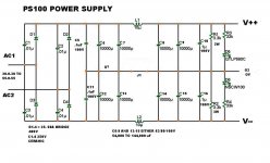
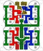
Those Sanwha capacitors were not only bigger ,but had a 22mm lead spacing/4 pin "footprint" , made me totally redesign the PS100 😡 . The power supply board can now accept 10mm , 18mm , 22mm , even 22mm/4-pin capacitors. 40mm is the max diameter supported ...(mine). I suppose I had to "pay the price" for caps that were almost free (swap-meet). Total size is 6" X 7" (150 X 175+ mm) , more room for the inductors , more fastons , and you might be able to do 100kuf @ 100V if you have a load of money $$$$ (12k@100v = 25-30usd apiece.) 😀
"PS100V1.2_complete.zip" is in the Mongrel folder , (below1/2) is the schema and new layout .. please inform of any errors.
OS
. The power supply board can now accept 10mm , 18mm , 22mm , even 22mm/4-pin capacitors. 40mm is the max diameter supported ...(mine). I suppose I had to "pay the price" for caps that were almost free (swap-meet). Total size is 6" X 7" (150 X 175+ mm) , more room for the inductors , more fastons , and you might be able to do 100kuf @ 100V if you have a load of money $$$$ (12k@100v = 25-30usd apiece.) 😀"PS100V1.2_complete.zip" is in the Mongrel folder , (below1/2) is the schema and new layout .. please inform of any errors.
OS
Attachments
Last edited:
Thank you, this is what I was asking for.Actually, the trafo is 54-0-54VAC
VAS current
Hi OS,
I just want to clarify:
Should we aim for 6.5mA (or thereabout) thru the VAS transistors?
I am currently have the following voltage reading:
Voltage across R24 (33R) = 0.205V (6.21mA) -> 6.21mA thru the VAS transistors
Voltage across R25 (68R) = 0.560V (8.24mA) -> 2mA thru the Green LED
Voltage across R8 (100R) = 0.285V (2.85mA) -> 1.175mA per CCS tail
The bias current (15mV across each Re) & output offset (<1mV) are stable.
Best regards, Stanley
Consider , with 3ma total tail current = 1.25 /q1 and 1.25ma/q2 + about .5ma to power the cascode Q3/4.
Also , VAS current 6.5ma through the main emitter resistors(r19/25) equates to about 4ma through the transistors (Q9-12) and 2.5ma through the LED's.
OS
Hi OS,
I just want to clarify:
Should we aim for 6.5mA (or thereabout) thru the VAS transistors?
I am currently have the following voltage reading:
Voltage across R24 (33R) = 0.205V (6.21mA) -> 6.21mA thru the VAS transistors
Voltage across R25 (68R) = 0.560V (8.24mA) -> 2mA thru the Green LED
Voltage across R8 (100R) = 0.285V (2.85mA) -> 1.175mA per CCS tail
The bias current (15mV across each Re) & output offset (<1mV) are stable.
Best regards, Stanley
Does it sound good? it should .... with the CCS adjust it is your preference how "hot" you run your semi's. What you describe current wise should be ideal. My setup is at a much higher voltage so my results may differ from yours. The GX was designed to work across a VERY wide range of supply voltages .
OS
OS
Experiment with the feedback cap (C3)
I followed KT's advice and used a 160uF/330V photoflash cap as the feedback cap (C3) on my GX1.2VB.
I have done some critical listening over the weekend. The GX has got extended high ranges & it sounds transparent & detailed. It does not sound quite right with the vocal & bass contents. It sound less impressive than my reference amp - AAK's SymAsym ver 1.3 with dual OTs.
Today I replaced the C3 with a Panasonic FC 470uF/16V low-impedance cap EEU-FC1C471 Panasonic Electronic Components Aluminum Electrolytic Capacitors - Leaded that I got in my part bin.
OS recommends 220uF/35V NP cap for this position. The original photoflash cap is only 160uF and it is quite old & of unknown quality. The Panasonic FC is bigger than recommended but it is a polar cap. This simple mod improve the sound quite a bit & I will do more comparison with my reference amp.
I found the Panasonic FC spec is very similar to the Nichicon PW series: UPW1C470MDD Nichicon Aluminum Electrolytic Capacitors - Leaded and they are used for Switching Power Supplies (Low lmpedance at 100kHz & High Reliability).
Cheers, Stanley
This is a very important phase in an amplifiers development .. The human feedback stage 🙂 . I also see need for improvement in the GX.
Since I now have the blameless to reference to and have that "modular" capability this should be very easy.
For the GX , I was thinking about
a.)changing the voltage on the input cascode or even eliminating it entirely.
B.) removing the 5pF lead compensation applied to NFB.
c.)experimenting with the 33R "magic resistors" or even eliminating them (jumper) to hear the resulting character changes.
Most of these "tweaks" would fall definitely in the "safe area" of this voltage stages design. This would be best done on my PB60/45V rail setup , which I am going to construct in the next day or so. In the end ME ,keen and you will all have the same "test bed" to do these subjective/objective refinements on.
I first have to build that monster PS100 along with the 4- PB60's to keep my promise AND have my test setup ( 45v safety).
OS
I'll soon be joining the Mongrel club. I have successfully made my boards and am waiting for some components to arrive. I'm using Stanley's PB120 and OS's GX PCB's, much thanks to you both for your hard work.
I am also waiting for some 'Hackercap' boards from a pinkfishmedia group buy for the power supply with 2 x 30-0-30 225VA toroids.
I have ordered UNITED CHEMI-CON|BSME350ELL221MK20S|CAPACITOR ALUM ELECT 220UF, 35V | Farnell Australia for C3. I hope this is ok.
One quick question, what size heatsinks are required for the PB120 running 40v rails? I have a couple of 300mm x 75mm x 48mm ,0.37 degrees C/W ones spare. Will one be enough for both channels or should I use one for each?
Thanks, Pete
do the sums.One quick question, what size heatsinks are required for the PB120 running 40v rails? I have a couple of 300mm x 75mm x 48mm ,0.37 degrees C/W ones spare. Will one be enough for both channels
What Re value do you intend to use?
What Vre do you think will suit that Re & your output transistors?
What is the quiescent dissipation of those output transistors?
Are you intending to maintain an average music signal of <=~-20dB ref maximum power for normal domestic listening?
What will be the temperature rise for two channels on your 0.37C/W sink?
you are guessing based on your experience.It will be more than enough for a home use.
I want him to go and work it out.
- Home
- Amplifiers
- Solid State
- The MONGREL (supersym II)