I modified the 1381/3503 models because they caused simulator errors with a certain circuit. I don't remember what I did. They are only Andy_C's if they have the _x suffix. I should have been more clear.
ARGH, I included the 15033/34, instead of the 34/35. Yes!!! Here is the proper include file uploaded.
- keantoken
ARGH, I included the 15033/34, instead of the 34/35. Yes!!! Here is the proper include file uploaded.
- keantoken
Attachments
Capacitor type for C8 & C10 on GX-VB
Hi OS,
I finally received my parts from Farnell today. I found one problem with the 0.68uF ceramic capacitor that I ordered for C8 & C10.
Manufacturer: KEMET
Order Code: 1168237
Manufacturer Part No: C330C684M5U5TA
Description CAPACITOR CERAMIC 0.68UF, 50V, Z5U, RADIAL
Dielectric Characteristic:Z5U
Capacitance:0.68µF
Capacitance Tolerance:± 20%
Voltage Rating:50V
Temperature Coefficient:+22%, -56%
Series:Gold Max
=-=-=
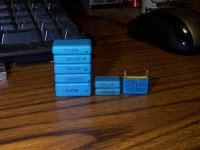
The .68uF Z5U cap is smaller than 0.01uF COG and it look like a monolithic ceramic cap.
My question are:
(1) What is the part number for your 0.68uF ceramic cap?
(2) Is it critical to use multilayer ceramic in this position?
(3) Is the value critical for C8 & C10?
I found a few 0.47uF 100V mylar caps in my parts bin, I may give them a try if they are suitable.
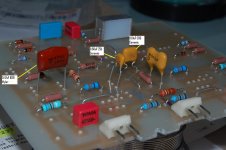
Attached is a picture showing the relative size of 0.68uF & 0.01uF.
Cheers, Stanley
Hi OS,
I finally received my parts from Farnell today. I found one problem with the 0.68uF ceramic capacitor that I ordered for C8 & C10.
Manufacturer: KEMET
Order Code: 1168237
Manufacturer Part No: C330C684M5U5TA
Description CAPACITOR CERAMIC 0.68UF, 50V, Z5U, RADIAL
Dielectric Characteristic:Z5U
Capacitance:0.68µF
Capacitance Tolerance:± 20%
Voltage Rating:50V
Temperature Coefficient:+22%, -56%
Series:Gold Max
=-=-=
The .68uF Z5U cap is smaller than 0.01uF COG and it look like a monolithic ceramic cap.
My question are:
(1) What is the part number for your 0.68uF ceramic cap?
(2) Is it critical to use multilayer ceramic in this position?
(3) Is the value critical for C8 & C10?
I found a few 0.47uF 100V mylar caps in my parts bin, I may give them a try if they are suitable.
Attached is a picture showing the relative size of 0.68uF & 0.01uF.
Cheers, Stanley
Attachments
Hi, sng. I used the .68uf's as this dropped the HF distortion of the GX from .01% to .002% as the bypass of the hawksford's emitter resistors. Their value is not truly critical as the effect (lower distortion) "kicks in" after .1uF. Your .47's should do nicely. I used this mouser part... DME1P68K-F Cornell Dubilier Polyester Film Capacitors .
Voltage wise you could even use a 25v device as there is only a volt max across the Re of the hawksford.
I still plan further GX development (swapping parts or changing values) mainly playing with the "magic resistor" values (R20/24) maybe even jumpering them to see what the audible effects are. When I have 2 low power PB60's in the "lab" , I can go crazy with the mods. This will be better as I will not be experimenting on a 250w unit (PB250- scary power and voltages) , I feel much more comfortable with 45-0-45VDC and only 1 pair OP'S !! 😱
Don't worry , the gx is as predictable as a simple bootstrap amp , and as reliable. I have successfully tested it with .9 - 1.7ma tail current , 3- 12ma VAS current (using the trimmers). the powerboard Vbias has enough range to accommodate these conditions but always start with the ops underbiased. The absolute best way to fire these up for the first time is to run the driver pair with 2 -33R temporary resistors tacked to the out/NFB point , adjust vbias for + - .5V ... then install OP's.
BTW your .47uF is in the wrong place .. it is where the trimmer should go!!
OS
Last edited:
SNG , what are those right angle edge connectors you use on the GX's ?? Doesn't have to be a part # , just what are they called ??
OS
OS
SNG , what are those right angle edge connectors you use on the GX's ?? Doesn't have to be a part # , just what are they called ??
OS
Hi OS,
Thanks for the reply. I googled the Kemet part number, it is a multilayer ceramic (Z5U is less stable than C0G).
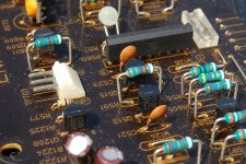
I salvaged the right-angle edge connector from the JVC amp. It was a 3-pin 0.1inch-pitch, I converted to 2-pin 0.2inch-pitch:-;
The closest replacement is molex 10-06-1025, which is still available on Farnell. MOLEX|10-06-1025|HEADER, R/A, SQUARE PIN, 0.2" | Farnell Australia , but Mouser does not stock this part.
The Molex 90121-0763 (Headers & Wire Housings 2.54MM CGRIDIII HDR 3P R/A SR SEL AU ), Mouser part number 538-90121-0763 may also be modified to fit.
I attached a picture of the JVC amp board, it was labeled as TP703 (Test Point), which fit for our purpose exactly.
Cheers, Stanley
Attachments
LED current
Hi OS,
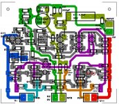
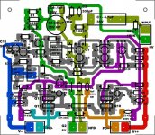
I found one error in the GX-VB overview. The polarity of LED (D5) is wrong, the anode of D5 should be connected to base of Q10. I found that out after power on the GX board, the D5 did not lit and that did not cause any disaster.
BTW, the green LEDs (D4 & D5) are only dimly lit. I measured the voltage drop across the LEDs:
Both D4 & D5 (Green LED) are 1.863V
D3 (I used a standard RED LED) is 1.860V
I tested the LEDs on a breadboard, the Green LED gives the following forward voltage drop:
1mA 1.864V
4.6mA 1.964V
15.4mA 2.128V
The RED LED gives the following forward voltage drop:
1mA 1.857V
4.6mA 1.960V
15.4mA 2.196V
Can you please measure your voltages with your GX1+PB60 at 45V supply?
Cheers, Stanley
Hi OS,
I found one error in the GX-VB overview. The polarity of LED (D5) is wrong, the anode of D5 should be connected to base of Q10. I found that out after power on the GX board, the D5 did not lit and that did not cause any disaster.
BTW, the green LEDs (D4 & D5) are only dimly lit. I measured the voltage drop across the LEDs:
Both D4 & D5 (Green LED) are 1.863V
D3 (I used a standard RED LED) is 1.860V
I tested the LEDs on a breadboard, the Green LED gives the following forward voltage drop:
1mA 1.864V
4.6mA 1.964V
15.4mA 2.128V
The RED LED gives the following forward voltage drop:
1mA 1.857V
4.6mA 1.960V
15.4mA 2.196V
Can you please measure your voltages with your GX1+PB60 at 45V supply?
Cheers, Stanley
Attachments
Using a + instead of "A" for Anode would be less confusing to some of us, who never learned the difference between Anode and Cathode.
- keantoken
- keantoken
Don't forget to pull those 2SA992/2SC2240 😉.I salvaged the right-angle edge connector from the JVC amp.
Recycle parts for GX & PB120LP
Hi Holger,
I used "recycled" 2SA970 & 2SC2240 transistors on the GX-VB. Four of 2SC2240s are B0 grade & they were Hfe matched at the factory.
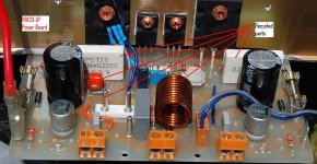
I also recycled the output coil & the MPC722 resistors on the PB120, the MPC722 resistors are compact & non-inductive.
I used the money saved to buy some premium resisters;-)
Cheers, Stanley
Don't forget to pull those 2SA992/2SC2240 😉.
Hi Holger,
I used "recycled" 2SA970 & 2SC2240 transistors on the GX-VB. Four of 2SC2240s are B0 grade & they were Hfe matched at the factory.
I also recycled the output coil & the MPC722 resistors on the PB120, the MPC722 resistors are compact & non-inductive.
I used the money saved to buy some premium resisters;-)
Cheers, Stanley
Attachments
SNG , glad you are at this point. I can't test at 45v anymore because I am done with my 75V setup. But , I will say if both green led's are on you have your cascode reference voltages. Mine were dim when I did my initial setup at 45V.
Other points to check are the emitters of Q1 and 2 , at both 45 and 75V they should be at -.7v . The bases of Q3/4 on your 45v setup should be around 7v.
measure across R22 (39k), it should be the sum of both rails minus 4-5v (90V for 45v rails). CCS adj. should be 100R ,LS adj should be 40R. The safest way to proceed at this point is to just hook up your drivers to create a small amp with 33R resistors going from the driver emitters to the NFB point (leave out the 68R).Adjust to +/- .5v with vbias. All set to put back the 68R and your OP's . 🙂
Tomorrow I will bring my 45-0-45v in the house and hook to a channel to get readings if this did not help.
OS
Voltage readings on my 42V rail
Thanks OS,
I have powered up the PB120LP with one pair of OT and no blue smoke. It is playing music and my first impression is very good.
I took the following voltage reading, they look alright to me:
Base of Q1 : -0.720V
Base of Q2 : -0.707V
Emitter of Q3 : +6.71V
Emitter of Q4 : +6.71V
Voltage across R22 : 76.9V for 42.2V rail.
I could not adjust the CCS tail current, I adjust the R7 from 0 to 200R, the voltage across R8 changed from 0.432V to 0.433V (2.2mA per tail). I guessed that I need to play around with R19/20/24/25.
The initial output offset was -24mV, I adjust R6 to get it down to about 10mV and use R12 to trim it down to less than 1mV.
The voltage across my 0.22ohm resistor is stable at about 16mV (71mA per OT).
Cheers, Stanley
Hi OS,
Some update, I rechecked the voltage across R8 after I adjusted the R6 & R12 to trim the output offset.
Voltage across R8 is now 0.336V (1.68mA per tail), the VAS transistors are running cooler.
I measured the temperature of the VAS heatsink, it was 42C(before I adjusted R6 R12), now it is 35C (ambient is the same 20C). Voltage across R24 (33R) is 0.341V (VAS current =10mA). Voltage across Emitter resister (0.22R) is rock stable at 16mV.
The CCS tail current is affected by adjusting R6 & R12.
Cheers, Stanley
Last edited:
Thanks OS,
I have powered up the PB120LP with one pair of OT and no blue smoke. It is playing music and my first impression is very good.
I took the following voltage reading, they look alright to me:
Base of Q1 : -0.720V
Base of Q2 : -0.707V
Emitter of Q3 : +6.71V
Emitter of Q4 : +6.71V
Voltage across R22 : 76.9V for 42.2V rail.
I could not adjust the CCS tail current, I adjust the R7 from 0 to 200R, the voltage across R8 changed from 0.432V to 0.433V (2.2mA per tail). I guessed that I need to play around with R19/20/24/25.
The initial output offset was -24mV, I adjust R6 to get it down to about 10mV and use R12 to trim it down to less than 1mV.
The voltage across my 0.22ohm resistor is stable at about 16mV (71mA per OT).
Cheers, Stanley
Let's start with R6 (CCS adj.) , you should be able to adjust between .6ma to over 2 ma per tail ... it sounds like you either have a solder bridge at the R6 traces or your R6 is defective. This should be set at 110R for the 1.2ma I am using.
For the R27 (LS adj.) while keeping your main offset (R12) centered , adjust for under 5mv offset... THEN go to R12 (main offset) , a half to full turn should get you under 1 mV. 🙂
15 mv for your .22R's should be @ 68ma per device which is optimal.
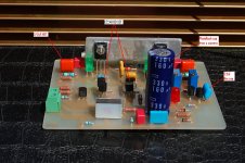
Attached is the overview so we speak of the same adjustments.
OS
Attachments
SNG, have you seen SMD power resistors? These are very non-inductive and compact.
- keantoken
Hi KT,
I have not heard about these SMD resistors.
I looked that up on Farnell, I spotted one problem with the WSR3R2000FEA (0.2ohm):
Voltage Rating:0.77V DC
The Dale datasheet uses an obscure formula: Maximum Working Voltage = (P x R)1/2
Otherwise they are great for emitter resistors, max value on Farnell is 0.2ohm though.
Cheers, Stanley
CCS current adjustment
Hi OS,
You are a champion, the problem is now solved. I used the R27 (the one closest to the edge) to adjust the CCS and of course that did not work - stupid me.
I have done the proper CCS adjustment and I am listening to the GX amp.
The VAS current does not follow your prediction.
Voltage across R8 = 0.255V (1.275mA per tail)
Voltage across R20 = 0.200V (VAS current = 6.06mA)
I am now running the following settings:
Voltage across R8 = 0.290V (1.45mA per tail)
Voltage across R20 = 0.213V (VAS current = 6.42mA)
So I am running the recommended VAS current but with a slightly higher tail current.
Cheers, Stanley
Consider , with 3ma total tail current = 1.25 /q1 and 1.25ma/q2 + about .5ma to power the cascode Q3/4.
Also , VAS current 6.5ma through the main emitter resistors(r19/25) equates to about 4ma through the transistors (Q9-12) and 2.5ma through the LED's.
OS
Some advice please.
I've looking at a 6/12 output Mongrel so looking at the easy ways to do this, we have both OS's and Alex MM PB250 to look at.
One question on Alex's design, there looksto be no diodes between the rails and NFB (D98, D99 from OS's PB250) and the 22uf caps have been added what affect would these two changes have?
Is there any benefit in adding these caps to OS's design?
Alex would you be OK if I take your board layout as a starting point for a 6/12 output version and post the layout?
Thanks
Rob
PMR is another acronym for Metallized polypropylene.
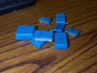
Got a bunch of these out of an old Apple computer monitor.
1PMR-100nF/630VAC EVOX RIFA Class X2 Case Capacitor
What!? Those are snubber capacitors! No way those could be good coupling caps, right!? haha lol
On the contrary, design for high-frequency pulse operation at hundreds of volts should make these caps excellent.
- keantoken
Attachments
Last edited:
- Home
- Amplifiers
- Solid State
- The MONGREL (supersym II)