Thanks
Bottom plate all hand made no machine to fold the back and front bits.
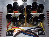
One question: I found in my parts bin(s) 4 Fukushima metal plate twin resistors ans I wonder if I can use this ones in the capacitor bank.
The schematic asks for 4 0.47 Ohms 3 or 5W and this ones are 2x0.47Ohms in one body but I don't know the power rating but they are about the double the size of the normal fukushima 0.47Ohms 5W.
I know they are toooo good for this application but that is what I have at hand at the moment.
The other thing is I need to change the board to fit this ones.
Ric
Bottom plate all hand made no machine to fold the back and front bits.
One question: I found in my parts bin(s) 4 Fukushima metal plate twin resistors ans I wonder if I can use this ones in the capacitor bank.
The schematic asks for 4 0.47 Ohms 3 or 5W and this ones are 2x0.47Ohms in one body but I don't know the power rating but they are about the double the size of the normal fukushima 0.47Ohms 5W.
I know they are toooo good for this application but that is what I have at hand at the moment.
The other thing is I need to change the board to fit this ones.
Ric
The ones holding the rails see only something like half a volt over them, 3W would be more than enough for those.
I do have 5W units installed but it runs so cool they may have been overkill, oh well its got to be good for thermal distortion.
I do have 5W units installed but it runs so cool they may have been overkill, oh well its got to be good for thermal distortion.
Two 0r47 in parallel have an effective resistance of 0r235.
Pass an ampere through them and you dissipate <500mW
Pass 2Adc and they dissipate <2W
Pass 4Adc and they dissipate ~7.5W
What is the bias/quiescent current that has to pass through these resistors?
Pass an ampere through them and you dissipate <500mW
Pass 2Adc and they dissipate <2W
Pass 4Adc and they dissipate ~7.5W
What is the bias/quiescent current that has to pass through these resistors?
Hummm, wait a minute...
I'm talking about the resistores in the power supply capacitor bank, you know the 2 banks separetaed by 4 0,47Ohms in each rail.
I'm using the power supply from the F4 manual
About the bias used by the output Fets depending on what my heatsinks can handle I will try to go for 1Amp bias
Found out the fukushima resistors are rated 5+5W with 3 leads, don't have a picture but they are the MPC725 (metal plate cement) 0.47Ohms
Last edited:
The R of your CRC, will run even cooler than my example figures show.
1A bias through 4 parallel connected 0r47 is just 29mW per resistor.
You could use 250mW or 500mW or 600mW.
You certainly don't need large Power Resistors.
1A bias through 4 parallel connected 0r47 is just 29mW per resistor.
You could use 250mW or 500mW or 600mW.
You certainly don't need large Power Resistors.
Buggerrrr....
Don't know what is going on with my board
It is the first time I just can manage to burn the image to the foto sense board even after 30 minutes exposure nothing happens
Normaly after 4/5 minutes is done but this time...
Is there any chance the foto filme on the board to go bad ?
Well going to buy a new one. 🙁
Using wrong type of light? Its only responsive to certain wavelengths. The Sun works, halogens, those bulbs that say "natural light" on them, seems lots of folks use fluorescent bulbs. Just wonder if you are using same bulb as previously or maybe bought some new bulb that is not giving you the right wavelengths.
Same light, is one of those exposure units you buy from electronic shops.
The thing with the board(s) I have is that I have them since my last project (F4) about 2 years ago and that's why I was tinking about the shelf life of them.
Ric
The thing with the board(s) I have is that I have them since my last project (F4) about 2 years ago and that's why I was tinking about the shelf life of them.
Ric
Look, I know toner transfer is a bi^(#, but man I am having great luck today and yesterday. My buddy Sonidos recommended new paper to me. I am using HP Presentation Paper 120g Glossy.
I have done 3 transfers. Two of them came out beautifully. Perfectly.
I am even getting away with a cheapo BROTHER Laser printer. Think its like a HL2140 or similar. Anyway, I make sure the print is ultra dark, photo mode, ultra contrast, B&W only, 1200dpi. Then hold the board and print super flat against each other and masking tape the entire edges. No bubbles of air or ridges of uneven paper between the tape outline. Iron on HI. 2 Steven Winwood songs later you are done. Put a piece of paper between the iron and the image paper for smooth movements. Hold down iron is one place at least 40 seconds and then move over a little. Outline will start to show through the paper. Where it is a bit less dark you need to keep hitting that part. Tip of iron is not as hot as center but does put down more pressure. When it looks like the image has nearly seeped through the paper to your side then youre done. Take the board to the bathroom and put it in the tub. Cold water. Remove it after few seconds and shampoo it. Seriously. Let shampoo sit there for a half minute and then immerse. A few minutes and you can rub a layer of paper off. Shampoo again. Immerse. Rub. When you start getting to copper dont get excited. Move on and keep getting a little paper off of the thing til its all got a tiny thin layer of paper left. Dont get worried to remove this. Be gentle with this last layer. Shampoo it again. Immerse. Now lightly remove the rest. Maybe toothbrush, maybe thumb. Man this worked out wonderfully for me. Best results I have ever had. Super super precise to.
Better than I had hoped for.
Anyway, I want to try photosensitive to but, today when this worked so well, I think I have a new standard to use.
Attachments
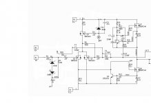
Alright, PSU is done without glitches. That's a happy thing.
I'm attaching my slight modifications to the schematic. I'm ditching the connection for the balanced input altogether - the extra resistors and zeners they result in. I'm also giving the zener reference a 3mA FET CCS instead of a resistor, because I'm swimming in FETs I don't know what to do with. Does anyone see problems here?
I'm attaching my slight modifications to the schematic. I'm ditching the connection for the balanced input altogether - the extra resistors and zeners they result in. I'm also giving the zener reference a 3mA FET CCS instead of a resistor, because I'm swimming in FETs I don't know what to do with. Does anyone see problems here?
Attachments
Last edited:
BTW, back on the soft-start topic - with my PSU and a 225VA transformer I don't seem to need a soft-start.
for 4 ohm speakers do we double the # of outputs?
Imix500 wrote:
I have 4 ohm speakers, and have BrianGT's boards (plus output boards if necessary).
My Transformer is also the Antek 300VA 2x15v. BrianGT power supply boards with 45k uF per rail.
If I were to use two output devices, instead of one, per rail, what could I expect power wise from this little monster? (My heatsinks are 9"x7"x1.25" with a variable speed fan).
-Chas
Imix500 wrote:
Dead quiet, around 11 Watts a side.
10mV and 25mV DC offset.
66k uF per rail, 300VA 2x15v and 25VA 2x9v Antek Toroids.
Softstart board from Rob Cheng.
Thermistor controlled fan on the tunnel heatsink.
I have 4 ohm speakers, and have BrianGT's boards (plus output boards if necessary).
My Transformer is also the Antek 300VA 2x15v. BrianGT power supply boards with 45k uF per rail.
If I were to use two output devices, instead of one, per rail, what could I expect power wise from this little monster? (My heatsinks are 9"x7"x1.25" with a variable speed fan).
-Chas
Doubling the output devices usually improves peak current delivery. As a side effect this can show up as reduced distortion into some loads particularly those below 8r0.
It can also be biased to allow more ClassA output current and this can result in more linear output when volume is higher.
But doubling of outputs does not double the power.
You may get an increase in maximum power of <=+1dB for the same distortion limits, but just as easily you may only see +0.1dB of extra power assessed the same way.
Last edited:
Yup, what Andrew said.
If you need more power you might as well jump up to the A30, which is almost what you have if you add another output pair to the mini.
If you need more power you might as well jump up to the A30, which is almost what you have if you add another output pair to the mini.
Heatsink limitations
Again, my heatsinks are 9"x7"x1.25" with a fan.
Just how big are the heatsinks required for proper cooling of an A30?
...If you need more power you might as well jump up to the A30...
Again, my heatsinks are 9"x7"x1.25" with a fan.
Just how big are the heatsinks required for proper cooling of an A30?
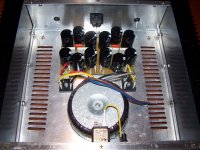
Is that mains to the fuse going in via the side terminal?
That increases the risk of fatality if someone takes off the fuse holder cover and touches the fuse end.
Why have you used yellow? It's a standard colour in 4 wire light switching, not mains cabling. Brown is Live, Blue is Neutral, Green/Yellow is PE/Earth.
That increases the risk of fatality if someone takes off the fuse holder cover and touches the fuse end.
Why have you used yellow? It's a standard colour in 4 wire light switching, not mains cabling. Brown is Live, Blue is Neutral, Green/Yellow is PE/Earth.
Hi Andrew
Thanks in point that out (yellow cable going to fuse)
I know the main cabling standart but in this case I don't have mains cable to do the job so I used what I had (16 gauge black/yellow/red/purple).
I work for the aircraft industry were we do the wiring looms for engines/wing etc but the cable is not suitable to be used in this (small) boxes.
Ric
rory1327 wrote:
I'm building basically the same amp as our friend above. Anyone here able to answer his question?
-Chas
I am starting to build a Mini-A (10W).
Working on PSU filtering. Considering a CLC. If there is residual ripple noise on the plus and minus rails does it cancel in the amp?
If I use inductors in each leg of the PSU and they are not well matched, is there a possibility that the two ripple currents could be shifted in phase, and thus additive, and thus create noise in the amp? Considering 30,000uf, 2.2mH, 15,000uf.
I'm building basically the same amp as our friend above. Anyone here able to answer his question?
-Chas
Member
Joined 2002
rory1327 wrote:
I'm building basically the same amp as our friend above. Anyone here able to answer his question?
-Chas
A crc psu is exactly what you want
Cap - Resistor - Cap.
and the aleph's are about 10-20 watts depending on rail voltage.
J'
- Home
- Amplifiers
- Pass Labs
- The Mini-A