Member
Joined 2002
I built my mini-A using BrianGT's BOM. What is its input (unbalanced) impedance? Am I correct into thinking it's ~50K?
Depends what schematic 🙂 If you look at the one above, its 10k if you want to make it 50k go for it 🙂
J'
I built my mini-A using BrianGT's BOM. What is its input (unbalanced) impedance? Am I correct into thinking it's ~50K?
Pretty close.
Thanks Bill!
jleaman, I thought that the resistors to ground should also be included when calculating the input impedance. BrianGT's mini-A schematic has a 10K input resistor and then there's those two parallel resistors to ground (R2:100K & R3:68K1) that make it ~50K.
jleaman, I thought that the resistors to ground should also be included when calculating the input impedance. BrianGT's mini-A schematic has a 10K input resistor and then there's those two parallel resistors to ground (R2:100K & R3:68K1) that make it ~50K.
Member
Joined 2002
Thanks Bill!
jleaman, I thought that the resistors to ground should also be included when calculating the input impedance. BrianGT's mini-A schematic has a 10K input resistor and then there's those two parallel resistors to ground (R2:100K & R3:68K1) that make it ~50K.
I was told it's the first resistor in the path, i could be wrong tho,
I'm thinking of making another mini-A... Could the more knowledgeable people here confirm the following?
Using BrianGT's schematic I think that:
R8 (221R): sets DC offset
R13 (47.5K): sets bias current
Correct?
My idea is to replace those resistors with trimpots and thus be able to tweak it to my heart's content. Has any body here done that already? Any problem leaving the trimpots in there permanently? Are 21 turns cermet trimpots a good choice? Any suggestions what kind of trimpot value to use?
Member
Joined 2002
I built the min a and left it all stock but used great HIGH quality parts and it sounds VERY nice!
Make no mistake, my current mini-A sounds very nice too! It's just that with a bit of tweaking (made easy by trimpots) it might get to sound even better.
As for parts, I used good quality parts, no exotics however.
As for parts, I used good quality parts, no exotics however.
Member
Joined 2002
Make no mistake, my current mini-A sounds very nice too! It's just that with a bit of tweaking (made easy by trimpots) it might get to sound even better.
As for parts, I used good quality parts, no exotics however.
Ive been so busy with work, i need to assemble my B1 and setup my mini's and buy 2 power amp cases for the amplifiers, then im good to go.
J'
My mini-A is disassembled ATM. I want a few things done.
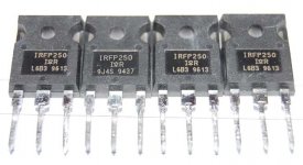
I layed my hands on four NOS IRFP250's. Only 1 euro a piece, pretty cheap, any plenty more where they came from...
Anybody here that made his mini-A using IRFP250's?
- add MKP1837 film caps accross the 220uF caps (done)
- replace bias resistors with trimpots (done)
- replace DC offset resistors with trimpots (done)
- re-do the screw holes for the MOSFETs (pending)
- get the gounding right (pending)
- maybe replace the IRFP240's with IRFP250's...
I layed my hands on four NOS IRFP250's. Only 1 euro a piece, pretty cheap, any plenty more where they came from...
Anybody here that made his mini-A using IRFP250's?
Attachments
Member
Joined 2002
My mini-A is disassembled ATM. I want a few things done.
- add MKP1837 film caps accross the 220uF caps (done)
- replace bias resistors with trimpots (done)
- replace DC offset resistors with trimpots (done)
- re-do the screw holes for the MOSFETs (pending)
- get the gounding right (pending)
- maybe replace the IRFP240's with IRFP250's...
I layed my hands on four NOS IRFP250's. Only 1 euro a piece, pretty cheap, any plenty more where they came from...
Anybody here that made his mini-A using IRFP250's?
Thats what i run in all 4 of my smd aleph mini's. IRFP240's 🙂
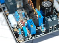
Yesterday I re-did the screw holes in the heatsinks. I got to use the drill-press-on-steroids at work. I used my own M3 tap set and successfully threaded the holes. The MOSFETs are now reliably fastened.
I built it per BrianGT's mini-A BOM and ended up with ~400mV accross the source resistors. This results in a bias of ~0.85 amps. Only recently I found this bit of info:
That does indeed match my observation, a 47.5K resistor gives a bit of a low-ish ~0.8 amp bias current.
I completely rewired the amp and implemented a starground. I also mounted the IRFP250's instead of the original IRFP240's I had in it. After powering it up I started tweaking the bias and DC offset. The trimpots really make adjusting the bias and DC offset very easy. Turn the bias pot up and the voltage drop over the source resistor goes up too. Cool. Over the course of the evening I adjusted left and right channel bias to 1.1 amps (heatsinks at ~37°C). DC offset in both channels is now below 10mV, one channel was 70mV before the tweak.
How does it sound? Well just like before I pulled it apart, only a touch better. A bit more clarity and depth. Even my wife said she noticed it, or perhaps she was just being nice and giving me the feeling I didn't waste my time this afternoon on my silly hobby... 🙂
I built it per BrianGT's mini-A BOM and ended up with ~400mV accross the source resistors. This results in a bias of ~0.85 amps. Only recently I found this bit of info:
- R13 is the bias resistor. Typically a 100k gives little over 1 amp, 150k 1.3 amp or so... 47k .8 amp
That does indeed match my observation, a 47.5K resistor gives a bit of a low-ish ~0.8 amp bias current.
I completely rewired the amp and implemented a starground. I also mounted the IRFP250's instead of the original IRFP240's I had in it. After powering it up I started tweaking the bias and DC offset. The trimpots really make adjusting the bias and DC offset very easy. Turn the bias pot up and the voltage drop over the source resistor goes up too. Cool. Over the course of the evening I adjusted left and right channel bias to 1.1 amps (heatsinks at ~37°C). DC offset in both channels is now below 10mV, one channel was 70mV before the tweak.
How does it sound? Well just like before I pulled it apart, only a touch better. A bit more clarity and depth. Even my wife said she noticed it, or perhaps she was just being nice and giving me the feeling I didn't waste my time this afternoon on my silly hobby... 🙂
Attachments
Member
Joined 2002
Yesterday I re-did the screw holes in the heatsinks. I got to use the drill-press-on-steroids at work. I used my own M3 tap set and successfully threaded the holes. The MOSFETs are now reliably fastened.
I built it per BrianGT's mini-A BOM and ended up with ~400mV accross the source resistors. This results in a bias of ~0.85 amps. Only recently I found this bit of info:
- R13 is the bias resistor. Typically a 100k gives little over 1 amp, 150k 1.3 amp or so... 47k .8 amp
That does indeed match my observation, a 47.5K resistor gives a bit of a low-ish ~0.8 amp bias current.
I completely rewired the amp and implemented a starground. I also mounted the IRFP250's instead of the original IRFP240's I had in it. After powering it up I started tweaking the bias and DC offset. The trimpots really make adjusting the bias and DC offset very easy. Turn the bias pot up and the voltage drop over the source resistor goes up too. Cool. Over the course of the evening I adjusted left and right channel bias to 1.1 amps (heatsinks at ~37°C). DC offset in both channels is now below 10mV, one channel was 70mV before the tweak.
How does it sound? Well just like before I pulled it apart, only a touch better. A bit more clarity and depth. Even my wife said she noticed it, or perhaps she was just being nice and giving me the feeling I didn't waste my time this afternoon on my silly hobby... 🙂
Good work, looks nice, i ditched the screw terminals for the power supply leads, I found them annoying and not needed.
Congrats! Looks like you have plenty of heatsink, I'd crank the bias up til you're at 50degrees or so.
change mini-a gain to 0DB
Hi, if I want change the mini-a gain to 0db.
Is possible to change the R1 to 10K to make it.
or I need change others?
Regards
John
Hi, if I want change the mini-a gain to 0db.
Is possible to change the R1 to 10K to make it.
or I need change others?
Regards
John
If I want to change it to 0db , I need change the R1 & R6 to 10K , right?
Thanks for helping
John
R6=R8=10K gain is 1+(R8/R6) = 2
if you want additionally smaller gain - increase R1 to 22K , and you'll get 6db of attenuation on input
if you want additionally smaller gain - increase R1 to 22K , and you'll get 6db of attenuation on input
R6=R8=10K gain is 1+(R8/R6) = 2
if you want additionally smaller gain - increase R1 to 22K , and you'll get 6db of attenuation on input
Hi,
Could I remov the R8 from the circuit? would it have any impact ?
thanks
John
Increase the Q1 current
Hi, Zen
Thanks for your helping again!
If I want to double the Q1 current , I plan to change as following
R4 =110R / R3=181R, should I modify R13 to 50r?
thanks
John
nope ;
it's conditio sine qua non for DC stability
Hi, Zen
Thanks for your helping again!
If I want to double the Q1 current , I plan to change as following
R4 =110R / R3=181R, should I modify R13 to 50r?
thanks
John
- Home
- Amplifiers
- Pass Labs
- The Mini-A