pooge said:This is what Oliver said in his paper, "Distortion in Complementary-Pair Class-B Amplifiers", in Hewlett-Packard Journal, vol 22, no. 6, p. 11-16, Feb 1971.
He was looking for an optimum value of output emitter resistor. He stated "To find an optimum R, we need only minimize the variation in output resistance with signal current."
He calculated an optimum bias of between 13 to 26 millvolts across each resistance.
I guess this demonstrates that old saying, "There is nothing new under the sun" 🙂. John Curl has talked about this same paper too. It sounds like a classic. If anyone has a PDF of this, or some other type of scan I'd love to read it.
Hi, Janneman,
I've got a dumb question 😀 Is it possible to get properties like you mentioned above with feedback amp? One example, how to make intentionally low damping factor with global feedback amp?
Of course there is! The changes in frequency response resulting from low of very low damping alone are massive. The distortion spectrum and ratio is also quite different. All differences that can be readily measured and documented. You really must be deaf if you would not hear that, even I hear it with my wooden ears!
I've got a dumb question 😀 Is it possible to get properties like you mentioned above with feedback amp? One example, how to make intentionally low damping factor with global feedback amp?
lumanauw
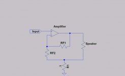
Easy, just use the negative current feedback circuit I've posted and damping will increase.
Easy, just use the negative current feedback circuit I've posted and damping will increase.
Hold It!
"Easy, just use the negative current feedback circuit I've posted and damping will decrease."
Don't do it!
The circuit is wrong!!!!
Sorry about it.
"Easy, just use the negative current feedback circuit I've posted and damping will decrease."
Don't do it!
The circuit is wrong!!!!
Sorry about it.
Hi, Jorge,
Have you built it? How does it sounds?
Mauro build similiar cct (but different) with gainclone.
What I'm thinking is decreasing, not increasing.Easy, just use the negative current feedback circuit I've posted and damping will increase.
Have you built it? How does it sounds?
Mauro build similiar cct (but different) with gainclone.
darkfenriz said:Yup
that's exactly what I was confused about😀
That's what happens when one should be in bed and is still at the keyboard...
🙁
lumanauw said:Hi, Jorge,
What I'm thinking is decreasing, not increasing.
Have you built it? How does it sounds?
Mauro build similiar cct (but different) with gainclone.
Again, I was with my head in other matters...
The circuit will DECREASE damping - rise output impedance. As I've said in the second post above, the 0.1 ohm resistor (very little loss) will behave as a 2 ohms resistor for a closed loop gain of 20 (or 1.5 for a gain of 15, etc)
I have not tested it in the last 40 yrs or about...
There was a time when some tube amps had a pot and a circuit similar to this one so user could adjust bass to his taste.
If you want to experiment, place a a low value trimpot (say 50 ohms) in parallel with the 0.1 ohms resistor.
With the pot at the ground side, output impedance will be the amp's plus 0.1 ohms, with the pot at the speaker side, it will be about 2 ohms (depending on amp gain, as stated above).
Use a fairly high wattage resistor for the 0.1 ohms (like 2W - parallel a few lower watt ones).
Hi Jorge,
A little warning: The relationship among an circuits with a good damping and a "good sound" is a lot of "ambiguous".
I have experimented launch "realities" circuits with technical even a lot of sofisiticate, but often the results are little "musical".
In this field is a lot of more important the " as " gets an objective that the "objective" same...
Ciao
Mauro
Ciao, Mauro
Nowhere I've said the sound is better - or worse - with different damping.
I will never get in such an argument - I'm still not ready for the mad house! 😀
As I've posted before, if one likes high FB SS - fine! If one likes SE tubes - fine!
To each his best liking.
lumanauw posted a question on how to increase output impedance using feedback, and I've posted a circuit.
If he will or won't like the results, it's up to him.
I feel we are in this forum to listen to all arguments, learn and try to advance a bit the general knowledge. At least, that's my case.
If you feel there may be a more refined circuit, I would be pleased to see it!
If you reverse it and use positive current feedback then output impedance can be reduced below zero and overall damping can be increased to infinity.
Mr Evil said:If you reverse it and use positive current feedback then output impedance can be reduced below zero and overall damping can be increased to infinity.
To almost infinity - it will oscllate by then...😀
I've never liked positive feedback in amplifiers due to it - high risk of instability.
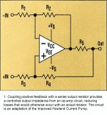
Hi lumanauw,
I use this configuration from about 10 years, to experiment any base theories using a chips amps.
The merits and the defects of this bridge, and of the "audio" results, that I have gotten with some circuits, are still in discussion ( have not still prepared a complete technical relationship on the My_Ref ).
From the technical point of view, this bridge is a lot of comfortable by dimensions, it has a differential input, and is easy to use it in " floating output "( output connected to a external voltage signal ), as in the case of the "stasis" configuration that had proposeded...
The "defect" is that is not possible ( in practice ) get high Zout at high frequency using the normal Chips amps (LM3886 etc)...
Ciao
Mauro
Great 3D!
Just discovered now this thread.
Lots (too much!) material to think about. It takes several days to me just to read the main posts.
My compliments to Mauro, I'm proud he's Italian.
There is an update summary of the item and methods discussed here?
Mauro visit us also in Italian audio DIY forums, please. We need You!
There is an update summary of the item and methods discussed here?
It's hard to get summary or a cct as end result here 😀
You can see in the thread "Back EMF - some considerations", up to 20 pages, members are still arguing wheter the back EMF is existed or not.
Hi Lumanauw.
I have pulled out of the thread you reference ( started by Jorge ) due to personal criticisms and 'smart-****' responses aimed at me; these being due to nothing less than a lack of necessary study and thorough 'pre-post' thinking.
Andy C. wrote that he was going to check out my suggestion that speaker cable induced voltage distortion arises due to series impedance and composite loading.
I very much look forward to reading his findings.
I have dug out and offer this test circuit as a starting point for anyone who doubts the existence of back-EMF, or its distorting influence upon hf audio reproduction.
Cheers ........... Graham.
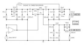
Graham Maynard said:Series inductance test circuit
Graham, what kind of wave is that input source on the left, the 2kHz? Does this circuit produce anything else than linear distortion?
Jan Didden
- Status
- Not open for further replies.
- Home
- Amplifiers
- Solid State
- The many faces of distortion