a "real" load; I don't have a "saved" slides, but a simple esample on a loudspeakers ESB QL65-A @3Vrms 1Khz (not high Back_EMF zone but I have "see" an analogue phenomena @ LC & Motor load at anothers frequencies). The amp not is DSLI but my 2030 high damping. When will have other measures on this load will show you.
Ciao
Mauro
Ciao
Mauro
Attachments
mauropenasa said:very divergent opinion by the majority of the members , and I believe that the back_EMF are able be a valid tool of reduction of the speaker THDS and IMD if the driver is able to " read it". My studies are slow, but I have elements to believe this...
Interesting idea... it may be... keep us informed!
BTW: what about the effects of the back_EMF on an overall NFB amplifier when sensing both output voltage and load current and applying similar amounts of NFB to both?

...that's what I have done on a test prototype (built around the "usual" LM3875), and indeed it does sound quite well... granted, it does sound much better than any other chip amplifier I've ever heard to date, and it also outperforms many expensive ("hi-end"!?) commercial solid-state amplifiers I have listened to. Compared to my own "real" (class A triode) amplifier, maybe it's not as good. But indeed it is not so far from it... and IMHO that's not a minor achievement for such a little, inexpensive class-AB solid state toy! 😎
Needless to say, all of this in spite of (or possibly DUE TO?!
 ) the fact that (obviously) the added amount of current NFB increases its out-Z to ~ 8ohm and thus its DF is ~ 1.
Hi Rodolfo,
mmh, I do not completely agree here. Quite some times, if you insist looking at the separate details, you end up missing the big picture...
Well, this would probably held true if our low-Z output was obtained by what you have called "passive" means... but I'm all but sure this is still valid when there is NFB involved... think of the random delays of these "added noise"... are you sure the NFB loop will always be able to properly cope with it?
Well, I'm not stating anything, but I wouldn't bet my life on that... 🙂
and anyway it is only possible to make progress by first segregating problems of different nature as much as feasible and tackling them one by one before reconstructing the complete picture.
mmh, I do not completely agree here. Quite some times, if you insist looking at the separate details, you end up missing the big picture...
With respect to microphonism, it was remarked in earlier posts that its magnitude is not only small, but also a low amplifier effective output impedance acts as a short circuit reducing even further its effects. The same goes for speaker distortion derived "back EMF".
Well, this would probably held true if our low-Z output was obtained by what you have called "passive" means... but I'm all but sure this is still valid when there is NFB involved... think of the random delays of these "added noise"... are you sure the NFB loop will always be able to properly cope with it?
Well, I'm not stating anything, but I wouldn't bet my life on that... 🙂

UnixMan said:Hi Rodolfo,
....Quite some times, if you insist looking at the separate details, you end up missing the big picture...
Sorry if I was not clear enough. Details should be addressed separately as long as possible. Of course one then must assemble the whole picture. What is impractical is to address all aspects toghether, for interactions and relationships become clouded.
.....Well, this would probably held true if our low-Z output was obtained by what you have called "passive" means...
Passive or active is irrelevant as long as the "black box" paradigm holds. For active output impedance reduction, bandwidth and power capability must be met.
Rodolfo
mauropenasa said:P.s: My measures are a "preliminary" value, and a "direct view" without
optimized. .....
Excellent Mauro.
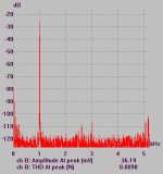
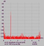
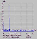
Now post #381 is resistive 8 ohm load and post #385 is corresponding voltage, so spectra should be identical. They are in quite close agreement, differences probably due to changes in measurement setup.
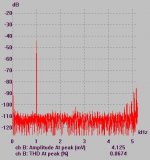
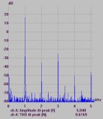
Post #384 I assume is current spectrum for same voltage as above. Not unexpectedly the load's nonlinear nature comes through.
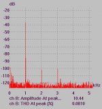
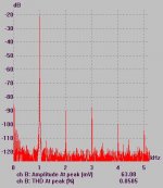
Then there are posts #388 for voltage and #389 for current. Problem is we do not know if this corresponds to the same amplifier (seems it is not), so we cannot segregate which distortion components are contributed by the amplifier itself, and what results from nonlinear loading on a relatively high output impedance one.
It should be important to get this clear. For example you can replace in this last case the speaker with a resistor and acquire voltage and current spectra for the same output voltage level.
Rodolfo
Hi Mikeks,
Re post 373. You write to me " You see, damping is a ratio ....."
Yes of course, and when applied to amplifier output it is normally expressed logarithmically or numerically eg. 1000, and called damping factor.
However the 'damped' *voltage* appearing at an amplifier's output terminal in response to the back-EMF modified loudspeaker current cannot be entirely in phase with either the amplified signal input or the loudspeaker current if the current generating output stage of the amplifier is itself inductive.
The relevence being that a new *voltage* component becomes additional distortion, and this is why I suggest that interested parties should make their distortion measurements using realistic loudspeaker loads or equivalents, as I have already demonstrated with Post#175. You could try it for yourself !
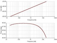
When a voltage generator is inserted in series with a passive resistor load then the transfer characteristic of the amplifier may be monitored at its output terminal.
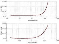
See attached amplitude/phase characteristics for the circuit I illustrated in Post#174.
Clearly that amplifier's output stage is inductive, and thus phase shifted load current is going to generate an error voltage, which if sufficient in level, could fractionally overcome forward output bias, as illustrated in Post#175.
A 4 transistor JLH amplifier might have a much lower damping factor say 30-32dB, but its angle is zero degrees at 1kHz and just +/-10 to 15 degrees at 100Hz and 10kHz depending on transistor choice and output capcitor value. Thus the out of phase component generated by the amplifier itself has a lower value.
Cheers ......... Graham.
Re post 373. You write to me " You see, damping is a ratio ....."
Yes of course, and when applied to amplifier output it is normally expressed logarithmically or numerically eg. 1000, and called damping factor.
However the 'damped' *voltage* appearing at an amplifier's output terminal in response to the back-EMF modified loudspeaker current cannot be entirely in phase with either the amplified signal input or the loudspeaker current if the current generating output stage of the amplifier is itself inductive.
The relevence being that a new *voltage* component becomes additional distortion, and this is why I suggest that interested parties should make their distortion measurements using realistic loudspeaker loads or equivalents, as I have already demonstrated with Post#175. You could try it for yourself !
When a voltage generator is inserted in series with a passive resistor load then the transfer characteristic of the amplifier may be monitored at its output terminal.
See attached amplitude/phase characteristics for the circuit I illustrated in Post#174.
Clearly that amplifier's output stage is inductive, and thus phase shifted load current is going to generate an error voltage, which if sufficient in level, could fractionally overcome forward output bias, as illustrated in Post#175.
A 4 transistor JLH amplifier might have a much lower damping factor say 30-32dB, but its angle is zero degrees at 1kHz and just +/-10 to 15 degrees at 100Hz and 10kHz depending on transistor choice and output capcitor value. Thus the out of phase component generated by the amplifier itself has a lower value.
Cheers ......... Graham.
Attachments
It is the neutral loudspeaker driving response of JLH based amplifiers that have always appealed to me, and yet even if you go up to 300-400W of heat dissipation they still do not have Pop-dynamics capabilities.
I have gone backwards and forwards though JLH based circuitry many times over the decades, and there has always been a trade off between phase coherent output damping and overall stability.
The attached amplifier is neutral, powerful, performs cleanly and has been nicely stable during use.
The next attachment shows its simulated output characteristic. Further improvement might be possible, but its already good, so I'm still thinking.
Cheers ........... Graham.
Attachments

With this graph I have created more confusion that clarity. How to have come early, they serve me time to catalog the data and write a complete relationship of objectives and conclusions( that I have already in my mind ). for the time being I want anticipate some points:
- In a dynamic loudspeaker it is not possible to separate it " not-linearity " from the " back_EMF " for the simple motive that the dynamics of operation imposes to the voice_coil to compensate all the variations( Re Le u B) with back_EMF. Is not a case if the point by and large emission of back_EMF it corresponds to the maximum mechanical excursion, that corresponds to the maximum phase delta, that corresponds to it mainly not-intrinsic linearity!
- The point of view of the amp (voltage) is entirely distinct from that of the loudspeaker, in theme of back_EMF. The amps of which have spoken in this thread worry to eliminate the voltage of back_EMF for non-being from it influenced. The loudspeakers want to go to the "vital" necessity of back_EMF because it is their "natural" damping ( on account of the reactions that provoke on the magnetic flux). The fact of have an elevated electric damping provokes the conversion of the voltage of back_EMF in currents. Datum that in the loudspeaker the generator of the movement is the current, determines a modulation of current that it may worsen the typical THD of the SPK.
- A lot of "critics" say that the Back_EMF is a phenomenon that has been "exaggerator" in this forum, and that if from it speak in improper way. If we look the problem from the point of view of the amp, the instrumental observations that I have done at the beginning of the thread show that to observe the phenomenon of IMD serve back_EMF to level much higher than that lifelike ( Back_EMF= -20dB to -40dB ), and my conclusion has been that nearly all the modern amps, they have a good immunity after IMD caused by back_EMF, quantifiable about to -80dB in the worse cases (1Khz). Because I persists in it mine searches on this phenomenon( and I contribute to increase the confusion )?
1. the Hiraga tests( and Graham ) show that not all the commercial amplifiers are do immune, overall at high-level. Any combinations are able producing IMD neighbours to 1%, surely audible. An underestimated thing is this high frequency phenomenon (10Khz). To depart the greater thing IMD of the majority of the amplifiers to this frequencies, the Back_EMF is limitate, but they hear again un that produced to low frequency, and the "real" IMD is able is greater of that theory.
2. It is possible that the influence of the amplifier on the Back_EMF is sub-judice of phenomenona of very greater ampleness in the spks. This element justifies a more in-depth study. The difference of performances among a driver current and a drive voltage, described scientifically they launch years will do, shows that the approach with a SPK is not discounted, but has to in operation be planned of the SPK and not of the amp.
I hope to have the time to elaborate my observations, completing the as always with technical solutions of evaluation (amps). Naturally I doesn't exclude the possibility to abandon( or doesn't end ) this studies, given that my work me from always less free time, and I extend to "saturate" my mind.
Ciao
Mauro
Hi, Mauro,
It's like thinking like Janneman with the "black box" approach. Only comparing input to output of speakers, and all non-linearity is classified as "speaker non-linearities", disregarding what element(s) are causing them. Like THD, it consist of many things that cause elements of THD, but "black box" approach only recognize 1 THD, not care about what is inside THD. Studying about what distortion(s) that makes the sum of THD can lead to lower THD, because each root of THD can be recognize and minimized.
So still using the same speaker but resulting in better audio, instead of using the same amp with the whole new designed speakers.
I think speaker non linearity and back EMF is difficult to separate because speaker's input is only 1pair (1+ and 1-).In a dynamic loudspeaker it is not possible to separate it " not-linearity " from the " back_EMF "
It's like thinking like Janneman with the "black box" approach. Only comparing input to output of speakers, and all non-linearity is classified as "speaker non-linearities", disregarding what element(s) are causing them. Like THD, it consist of many things that cause elements of THD, but "black box" approach only recognize 1 THD, not care about what is inside THD. Studying about what distortion(s) that makes the sum of THD can lead to lower THD, because each root of THD can be recognize and minimized.
Jorge started a thread about this, and a senior member seems to think that "back EMF problem" does not exist. Maybe all this long, it is already inside the "speaker non-linearity" since the 70's. But recognizing what is (are) inside speaker non-linearity could result in smaller speaker distortion (if it is connected to amplifier)A lot of "critics" say that the Back_EMF is a phenomenon that has been "exaggerator" in this forum, and that if from it speak in improper way.
Since we are in "solid state" forum and not in "loudspeaker forum", lets change how to minimize the distortion (that is caused by interaction of amplifier+speaker) from the point of view of the amplifier (how to make an amplifier that makes that distortion/amp-speaker interaction lower).but has to in operation be planned of the SPK and not of the amp.
So still using the same speaker but resulting in better audio, instead of using the same amp with the whole new designed speakers.
If we take 3 stages power amp+feedback as standard, there are some amps that sounds different than that "standard"
Consider the connection of amplifier and speaker as bidirectional connection, then there seems there are 2 things can be done by our current knowledge of how to make audio power amps.
1. Advoid that bidirectional communication between power amp and speaker. That is to use non-feedback or non-global feedback. By this approach, the relation of signal only 1 way, that is from amp to speaker direction. Charles Hansen said that using feedback is always "dead end". People like Nelson Pass and John Curl actually likes to use no-feedback whenever they can (or use low feedback). Lars Clausen.
2. Still using feedback, confronting that interaction of power amp and speaker, with some topology, like :
-using few stages, like JLH/Graham Maynard
-using NP's SUSY, where the back-EMF is put in both side of differential.
Like Janneman said, feedback has lots of advantage. There must be a way to still using feedback, but without the "interaction" problem.
lumanauw said:There must be a way to still using feedback, but without the "interaction" problem.
Well, you could build a good linear amplifier that makes few
assumptions about the load.
lumanauw said:But recognizing what is (are) inside speaker non-linearity could result in smaller speaker distortion (if it is connected to amplifier)
Ah! that's the point.
Mauro's data shows there's a lot going on in the amp-speaker interface, and I really believe it does not depends on using feedback or not
For me, the best way is to have a low value open loop output impedance; others think the opposite.
There may be advantages in a higher source impedance to drive a speaker at lower frequencies, but then speakers/boxes/Xovers have to be designed taking this in account.
Would Bi ampli be the best path?
- Status
- Not open for further replies.
- Home
- Amplifiers
- Solid State
- The many faces of distortion