Hi, Unixman,Sure. But try also the following... attach a flywheel to a DC motor shaft and let it run until the speed stabilize. Then, suddenly invert the DC voltage polarity and watch it draw even more current until the shaft slows down, stops and eventually begins to rotate the other way around accordingly to the new voltage polarity.
Makes me think. If at a certain t=0, the speaker's excursion is at +5mm. At t+1, the music demands the speaker's excursion is at -5mm, while it is still sitting at +5mm, not 0mm. The speaker will draw more current from the amp due to reversed EMF condition?
AKSA said:....I would like to comment on the disillusionment I see creeping in that no one notices, there is no response, and who cares anyway.....
Thanks for your comments Hugh, but as posted earlier with reference to Andy's observation, what I find disgusting is the insistence on the same already flagged errors as if the (at least from me) respectful observations / corrections had never been made.
Rodolfo
lumanauw said:
Makes me think. If at a certain t=0, the speaker's excursion is at +5mm. At t+1, the music demands the speaker's excursion is at -5mm, while it is still sitting at +5mm, not 0mm. The speaker will draw more current from the amp due to reversed EMF condition?
Yes and no. What actually matters is not the absolute position, but the direction and the speed. The direction determines the back-EMF polarity, while the speed determines its magnitude.
Hi all,
I'm lost.
A lot of members has listed the launch problems tied to the analysis on SPKs and amps, some not doesn't want feel speak of " Back_EMF ", other assemble on the damping and phase Distortions. I feel me in similar way to Lumanauw, I understand the theme but doesn't more know that behaviour conclusion. A positive element of some emersed test in this Thread is that are effective ( independently from the topology and from the sub-judice of the problems ), how to the analysis " reverse driven " proposed by Graham.
The #447 post of Rodolfo is a lot of lifelike and shareable.
I have started a series of test looking for some answered in the V/I relationships of output, but is a lot of difficult isolates the problems in staticses conditioning. It does emersed safety catch from my test is that the "dynamic" behaviour of an current amp on the load is much distinct from that of an voltage amp. The first interesting thing is that an current amp has not to compensate the variations of phase of the load, because he maintains constantly in phase with the output current. This farewell for any condition when Zout > Zload.
This characteristic avoids it conditions of extra-currents that the voltage amp has to produce to "compensate" the phase variations.
The second is that the THd of the SPK+amp in voltage driven is present on the current, while in current driven is on the voltage. In the mixed circuits (voltage driven whith Zout close loop = Zload ) create "mixed" situations ( partial phase-shift and U/I distribution THD ).
Graham insists much on the problem of the induced bewilderments by the crossover of the spks, but if you is observed the "theorists" circuits, practically all the "critics" reactive components am crossed by the same current and then in phase. The only problem is that is reduced the effect of the " in parallel " components and of aftermath the damping studied for a voltage driven.
Conclusion: the advantages of reduction of the not-linearity of cable+spks using a current driven is a lot of greater of the drawbacks. If use a technique of "dynamics equalization" of the output current, in degree to eliminate the only thing caused drawback by the "not damping voltage ". Does it unusual is that nearly all am oriented in he shows the contrary thing of the my "obvious" and "mathematicses" conclusions ( in fact have not still seen a reference embodies to a mathematical function in degree to show the advantages of the voltage driven).
I don't say that a normal amp voltage doesn't work or is not suited to reproduce it "good music". To say only that exist working hypothesis more "stimulants" than the usual "power opamp" to reproduce sets to music.
A last thing that wants say is that the experiences of this complete monthes have confirmed that the BacK_EMF am not " the problem " of the power amp ( not it never am been!), but their study allows to analyse the amp from a point of view more selective and more profitable. the example of the " reverse driven " is the more evident.
This is my point of view and is not a criticism to other point of view...
Ciao
mauro
Makes me think. If at a certain t=0, the speaker's excursion is at +5mm. At t+1, the music demands the speaker's excursion is at -5mm, while it is still sitting at +5mm, not 0mm. The speaker will draw more current from the amp due to reversed EMF condition
This would suggest that the loudspeaker was not well suited to the task for example using a woofer as a tweeter. In normal operation the speaker will follow closely the input signal the difference between the back emf and the driving voltage being what generates the force to move the cone.
Stuart
mauropenasa said:.... behaviour of an current amp on the load is much distinct from that of an voltage amp. The first interesting thing is that an current amp has not to compensate the variations of phase of the load, because he maintains constantly in phase with the output current....
Mauro, you may want to check my earlier posts on another thread here regarding V - I relationships under reactive load and for both current and voltage mode drive. Don't forget you are feeding back (output) voltage in your reference design.
Rodolfo
Excellent work, Rudolfo.
My evaluations on the current driven obviously is not directly connected to my MY_ref circuit, because its general operation is that of an ordinary voltage amp. Eventually his internal dynamicses am different ( or much diverged ) from a classical voltage amp.
My idea is tied up to study of "non conventionals" structures of fashion in this moment, as the firstwatt and some single ended borrowed from the valves, over that from my irregular experiments with the " current pump ".
In connection with the results of your analysis, I consider them an objective and well exhibited data ( I observe this behaviours on my tools from a lot of years ). It is the choice of the planner decide like stage is more suited to the audio reproduction. If observe the graph of D.Self concern to " large signal distortion ", they improve performances are not tied up tightly to the voltage swing of the output device but to they current. I prefer exploit a power opamp ( or her output stage ) in voltage swing that in her current swing , and this begins ( in part ) it is applied to the operation of the current pump that use for a long time. The "statics" THD increases at high-level of more that in the classical circuits, but it is more reduced in dynamicses conditions especially with reactive loading . But this talked am not tied up in the back_EMF and then I close my digression
...
ciao
Mauro
mauropenasa said:... But this talked am not tied up in the back_EMF and then I close my digression ...
No digression here Mauro, this thread is "The many faces of distortion", so your post is competely relevant.
Rodolfo
One point to be taken in consideration is that there's no such a thing as 'instant movement' in a speaker.
Audio signal exists in frequencies up to 20kHz, what from an electronics viewpoint is an eternity (tens of gigahertz are used routinelly in telecom).
And a speaker cone amplitude falls with rising frequencies.
So, if a speaker is moving 'fast', it's moving very little. And, if it's moving a lot, it's moving slowly.
Of course, in a wide range speaker one may have lows and highs at the same time, so an small amplitude movement (highs) will ride a large amplitude wave (bass), and in real world equipment IMD will result.
I have never understood this rush about the "back EMF" from the speaker. In fact the speaker acts as a an RL series circuit (voice coil resistance and inductance) followed by parallel RLC circuit, representing mechanical/acoustical circuit converted to electrical side. All of those thoughts about moving speaker mass, compliance etc. are described by this parallel RLC circuit. All of the mystery shown here is nothing more than gossip.
There is the same voltage and current as generated by the parallel RLC circuit (Res, Les and Ces) in series with serial RL circuit (Re, Le). I do not know if the current response of this circuit can be called as "avalanche". There is no need to "visualize" speaker cone movement when speaking about the response. Simple help, but mystifying.
MikeB said:So, avalanche current generated by these coils is mystery/gossip/negligible ?
I've never heard about 'avalanche' (in speakers) before.
Any links to some article/posting?
Thanks,
Hi PMA,
Re Post#472. Aha !
But cable/source impedance is in series with the crossover network ( not just the drivers with their whacking great series resistance ) and this is where I believe an error is generated that is subsequently fed to the drivers due to there being greater additional energy components within the wave than are normally 'visualised'.
__________________________________________
However, I have given up trying to translate my understanding because I realise that it is like trying to challenge a religion. I cannot explain in terms that the listener won't accept, and thus it is me who is seen to hold misguided beliefs.
Correct ? Imaged proof becomes the only answer !
___________________________________________
Is there *ANYONE* who can run a 20kHz bandwidth wav.file into the 2003 circuit in my Post#439 above;-
to check if dynamically changing drive in the mid-bass frequency range, induces error perceivable in the treble output ? I think the crossover frequency is about 6kHz.
An error that could not be there without choke/series impedance.
Cheers ........ Graham.
Graham Maynard said:Is there *ANYONE* who can run a 20kHz bandwidth wav.file into the 2003 circuit in my Post#439 above
Graham, it is morning here, and as I said I am going to try this out. First I need to write some code to convert my stereo WAV files to mono. This isn't very complex, but your patience is requested as the normal day-to-day requirements of living also occupy my time. I'll report some results Sunday.
I have some questions about your test circuit.. It looks like an ideal amplifier driving two simulated speakers, except that one simulated speaker has no woofer section. Now, I'm guessing that the parall R-L network of 8.2 Ohms and 6 uH is meant to model the amplifier's output inductor circuit, right? I'm also guessing that this is meant to be an argument against using output inductors. If that is so, then I'd propose the following change.
1) Make the simulated speakers identical, both with woofer and tweeter sections.
2) Drive one simulated speaker straight from the zero impedance source, and the other via a parallel R-L circuit.
3) Define the error signal as the difference between the tweeter simulated outputs.
I think this would represent a more realistic scenario, namely "identical speakers with two different amplifiers" and as such it directly addresses the issue of the output inductor.
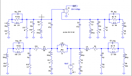
Secondly, it appears that the driver portion of your simulated speaker is exactly identical to what PMA described in his earlier post. Namely, a series R-L circuit in series with a parallel RLC circuit. See the far right side of this diagram.. If we can agree that the back EMF of the speaker is completely modeled by this parallel RLC network, then I think it's safe to say that the entire discussion has been a misunderstanding in which the two sides of the issue are talking about the exact same thing in two different ways.
Here's an example of what I'd propose to test. Identical networks on the left and right, except that one is driven from an ideal amplifier output, while the other is driven from an ideal amplifier with an output inductor network. The error voltage between the tweeters is at the top and represented by the unity gain voltage-controlled voltage source measuring the voltage difference between the tweeters.
I've updated the speaker model to reflect some of Graham's later posts, which show some resistors in series with the crossover network inductors that weren't shown in Graham's earlier version of the speaker models.
I've updated the speaker model to reflect some of Graham's later posts, which show some resistors in series with the crossover network inductors that weren't shown in Graham's earlier version of the speaker models.
Attachments
Forgive me if I missed something in this long thread, and out of sheer ignorance:
Why and how can one model an electrodynamic speaker's behaviour by a simple R - L - C network?
Does the real speaker's voice coil not reside in a magnetic field in addition to its RLC characteristics?
Does the condition of modulated current in a coil in a magnetic field not automatically create reactivity in addition to an RLC model? To complicate the matter, that coil with the modulated current in it moves inside the magnetic field as well, doesn't it?
In addition - if "back-EMF" (no matter what word used) did not represent a significant problem for amplifiers, why do, for instance, application notes for chip amps show clamping/flyback diodes etc, when used as motor drivers?
MBK said:Why and how can one model an electrodynamic speaker's behaviour by a simple R - L - C network?
The theory of all this is given in the works of Thiele and Small which in turn were based on the work of Beranek. Here is a link to a description of Beranek's book.
There were two papers on this by Thiele in the AES Journal. The titles are:
"Loudspeakers In Vented Boxes: Part I"
"Loudspeakers In Vented Boxes: Part II"
and two by Small (who did his PhD dissertation on speakers), titled:
"Closed-Box Loudspeaker Systems Part I: Analysis"
"Closed-Box Loudspeaker Systems Part II: Synthesis"
The whole thing is way too complex to get into here. I could provide these by email on request.
Hi Andy,
I meant my question in the context of 'back-EMF: important or non-existent', and the proposed test circuit. Will an RLC network give a realistic model of the electrical reactivity of a coil having modulated current flowing through it while moving nonlinearly inside a magnetic field?
I haven't read the original Thile and Small papers but AFAIK they were concerned with modeling the electromechanics of the speaker mass-damping system through an RLC analogy (thereby providing means to control, EQ, etc, the speaker, using RLC derived electrical filters). But my question here was, can one model the purely electrical properties of a dynamically driven speaker solely by RLC - specifically, the coil acting as a nonlinear generator of its own in the dynamic speaker case. I guess assuming perfect damping one could, but the issue in this thread as I understand it, is what artefacts does the speaker-amplifier system produce during artefacts while 'attempting' such damping during transients.
When we use DC relay (like 12V DC relay), it is always to use diode // to the coil, to give it circular path for spikes, because that spikes can kick back to the relay driver.for instance, application notes for chip amps show clamping/flyback diodes etc, when used as motor drivers?
- Status
- Not open for further replies.
- Home
- Amplifiers
- Solid State
- The many faces of distortion