MBK said:I meant my question in the context of 'back-EMF: important or non-existent', and the proposed test circuit. Will an RLC network give a realistic model of the electrical reactivity of a coil having modulated current flowing through it while moving nonlinearly inside a magnetic field?
Let's back up a bit and discuss this in a general way, keeping in mind that I'm not a loudspeaker expert by any stretch of the imagination. I have read the Thiele and Small papers, but that was many years ago when I was in college, where we studied them in a class I had in the late '70s. But I haven't studied them much since.
First, can the speaker be considered to be purely linear in the strict sense of the word? In the strict sense of the word, no. To model exact behavior, nonlinearity must be considered. However, if one insists on doing so, the math becomes completely intractable, so that only numerical results, not closed-form solutions to problems, can be found.
Second, is there any advantage to approximating them as linear systems? You bet there is!!! Without the linear systems approximation, none of the fundamental results predicting low-frequency response, impedance vs. frequency, or any of the well-known design equations woudl be possible. Further, these approximations have been shown for many years to be reasonably accurate and extremely useful for design work.
Third, assuming a linear system, how is the back EMF represented? It's represented with the parallel RLC circuit of the previous posts and also in Graham's equivalent circuit. That's only valid for closed-box and infinite baffle systems. A more complex result is given by Thiele for vented box systems.
The equivalent circuit was a slight modification of one given by Graham, and all the issues I know of that he's been bringing up in the context of back EMF are related to linear circuits.
Hi Andy, (written 7:15, I see you have another post which I am about to read)
I had thought you intended to apply your wav.file to the input of an amplifier looking for amp probs. I have amplifier-speaker interface test circuitry here too.
Of course I can be patient - I've (we've all) waited long enough already.
Re your points 1,2 and 3 in Post#475. Yes this is to show output choke induced error, but it is easy to substitute some cable parameters too. Also by adding say 0.39ohms of series resistance the same test might show different levels of induced tweeter error in the cable-loudspeaker system as when driven by a 'tube' amplifier.
The only difference between the two halves in circuit#439 is the presence of the mid/bass section/driver. The sine group delay to the tweeter sections via the damped series output choke will be the same. If there were no choke there could not be any error; period.
If one half has a choke and the other not, as in your circuit, there will be a naturally occuring choke delay that will increase error with frequency, and this will be present between the two halves but inseparable from the combined error. Your additional resistors are in my later circuits, but they will make negligible difference due to there being other series resistance. Go ahead with them though.
Misunderstanding ?
Maybe we best not go there !
A realisation in the form of results will help everyone.
Hi MBK,
All valid points. At this stage we are discussing the simulation of basic electrical characteristics, not transduction capabilities.
This is not amplifier-speaker, but cable-speaker with a perfect voltage amplifier output; ie. ultra-high damping solid state.
Cheers ........ Graham.
Graham Maynard said:If one half has a choke and the other not, as in your circuit, there will be a naturally occuring choke delay that will increase error with frequency, and this will be present between the two halves but inseparable from the combined error.
Okay, I think I see what you're saying. With the RL amplifier output circuit, one could say that there's two errors:
1) An error due to the series impedance of the RL network changing the transfer function from the source to the tweeter.
2) Another error, also due indirectly to the series impedance of the RL network. This error is an interaction of the high-pass and low-pass sections which also changes the transfer function from the source to the tweeter.
In your original circuit, removing the woofer section from one of the speaker models was intended to isolate error 2 above.
MBK said:
I haven't read the original Thile and Small papers but AFAIK they were concerned with modeling the electromechanics of the speaker mass-damping system through an RLC analogy (thereby providing means to control, EQ, etc, the speaker, using RLC derived electrical filters). But my question here was, can one model the purely electrical properties of a dynamically driven speaker solely by RLC - specifically, the coil acting as a nonlinear generator of its own in the dynamic speaker case.
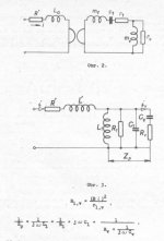
Well - yes, we can. I am attaching an image showing how to transfer mechanical impedances (both speaker and air on membrane) to the electrical circuit. The model is pretty good, but detailed explanation requires study of electro-acoustics.
I would like to excuse myself from any longer discussion on this topic.
Attachments
Hi guys,
as I see the thread going and soon will be provided perhaps by Andy C some simulation results I would like to point out that if you want to simulate "large signal" back EMF artifacts you should substitute the loudspeaker coil inductance with and core wounded inductor that get's saturated, eg. corresponding to the VC moving out of it's linear working area.
When the VC moves outside of the magnetgap in most ordinary loudspeaker elements it moves outside from a region where's magnetical material conductng the magnetic flux field and thereby the inductance is decreasing.
This will give diffrent and more realistic result, good luck with back EMF the simulations.
Cheers Michael
Hi Michael,
Well, I'm still not quite finished with my program for converting WAV files to mono, but it will be done tomorrow morning. This was my first time writing code to mess with WAV files. I'm sure I could have found a utility on the net to do this, but I want to learn to do my own DSP code in C++, so this is a good first exercise.
To be honest though, I still don't see the relationship of the simulation to any of the discussion of back EMF nor do I see what it will resolve. If it weren't for the fact that I can use this code for other things, I'd likely conclude that it's a waste of time. However, the audibility (or not) of the output inductor with bandlimited source material is an issue that interests me, so all is not lost I guess.
Ultima Thule said:Hi guys,
as I see the thread going and soon will be provided perhaps by Andy C some simulation results I would like to point out that if you want to simulate "large signal" back EMF artifacts you should substitute the loudspeaker coil inductance with and core wounded inductor that get's saturated, eg. corresponding to the VC moving out of it's linear working area.
Hi Michael,
I hope there is no misunderstanding. The RLC parallel resonant circuit (R1, L1, C1 in the attached image) is a model for mechanical speaker behavior, not voice coil inductance. The voice coil inductance is represented by L2. See the difference in L1, L2 inductance values. L2 (voice coil) causes only impedance increase on higher frequencies. L1 is reponsible for speaker low frequency resonance.
The so-called "back EMF" is nothing else than energy exchange.
Attachments

Hi Andy,
Suddenly changing waveforms in the range that drive the mid-bass also carry other higher frequency components that would normally drive the tweeter. These components will energise both of the #439 tweeter circuits and thus cancel.
The purpose of this test is to show whether there are any impedance transformed mid/bass generated back-EMF components altering the tweeter waveform; ie. to prove why there should not be a choke, and thus why bi/tri-wiring should be used.
I have entered the test circuit here because it relates to one form of distortion.
Hi Michael,
As a voice coil moves through its poles the inductance/back-EMF immediately becomes reduced and it resistively dissipates more heat without any hysterisis delay due to there being a greater winding proportion existing as non-saturating air core.
Is a saturating core a valid simulation equivalent throughout the working frequency range of a loudspeaker; ie. for music waveform energisation ?
Cheers ........ Graham
Hi all,
hmm,
seems me that the discussion is entering much of more in the dynamicses of the crossover filters that in that of the amp interface.
A good knowledge of the operation of the dynamic spk is important for the finalization of the amp ( and my discussion with lumanauw from it is the evidence ), but the reasonings on the delays of phase on the Tweeters ( and as oppose them ) in accordance with me invade the ground of the specialists of planning of SPKs.
I want remember that on the techniques of power factor correction and of "temporaly alignment" of the acoustic drivers there are studies and brevets well more sinks than our electrics models. The risk is to get un results optimized on 1 models of SPK and mediocrities on other.
In connection with the cables, some has thought about the behaviour of a "shield" spks cables ? ( reduces the Lserie because short-circuits all the electromagnetic issued components )...
Ciao
Mauro
Windows Sound Recorder
You don't even have to search and download something. Even Windows Sound Recorder (that comes with Windows (In WinME: Start>Programs>Accessories>Entertainment>Sound Recorder) is able to convert a stereo WAV file into a mono one, via File>Properties>Convert Now... It can also do sample rate conversion, but it is very lousy in doing so, probably no good aliasing filters inside. Then better use a free program like r8brain. But for stereo to mono at the same sample rate, it works fine.
Steven
andy_c said:
Well, I'm still not quite finished with my program for converting WAV files to mono, but it will be done tomorrow morning. This was my first time writing code to mess with WAV files. I'm sure I could have found a utility on the net to do this, but I want to learn to do my own DSP code in C++, so this is a good first exercise.
You don't even have to search and download something. Even Windows Sound Recorder (that comes with Windows (In WinME: Start>Programs>Accessories>Entertainment>Sound Recorder) is able to convert a stereo WAV file into a mono one, via File>Properties>Convert Now... It can also do sample rate conversion, but it is very lousy in doing so, probably no good aliasing filters inside. Then better use a free program like r8brain. But for stereo to mono at the same sample rate, it works fine.
Steven
Hi Andy !
Some minor comments on your sourcecode...
You shouldn't round sounddata symetrically around zero, this
introduces crossoverdistortion.
The correct roundingfunction would be "floor(Val+0.5)".
For adding 2 samples it would be enough to use the following:
"return( ((long)left + (long)right + 1)>>1 )"
😉 (Can't live without optimizing...)
Mike
MikeB said:You shouldn't round sounddata symetrically around zero, this
introduces crossoverdistortion.
The correct roundingfunction would be "floor(Val+0.5)".
Hmm, I'll have to think about that one. I've been doing graphics programming for a while, and we do the symmetric rounding there. I'll change it. Do you know of a good book that covers sound file programming? I couldn't get the info I needed from MSDN and ended up grabbing some code to process the WAV header info from the Borland site.
For adding 2 samples it would be enough to use the following:
"return( ((long)left + (long)right + 1)>>1 )"
I thought the effect of a right shift was implementation-defined when the integers are signed? I could be mistaken though. My copy of Harbison and Steele is at work.
At the moment, my Squeezebox software is refusing to play the LTSpice output file. I'm guessing it may be because of the use of WAVEFORMATEXTENSIBLE. I'll be able to check that with my code in the debugg_er. ROFL! I had to put the underscore in the debug word because of the automatic censorship software

UnixMan said:
Sure. But try also the following... attach a flywheel to a DC motor shaft and let it run until the speed stabilize. Then, suddenly invert the DC voltage polarity and watch it draw even morecurrent until the shaft slows down, stops and eventually begins to rotate the other way around accordingly to the new voltage polarity. 😉
This is the basis of Matti Otala's 1980'ies tests with very special waveforms on speakers. Put a step function into the speaker, and when iit's velocity is max, reverse the step function. Brutal! Of course you see huge currents that make it look like a one ohms speaker. However, I don't see any link with music reproduction.
That is (still) my objection to Grahams basic tenet. First cycle distortion disappears if you input a bandlimited signal, your test signal becomes just a mix of sine waves, damped, bandlimited. No sudden transients. The remaining distortion is LINEAR, meaning freq response deviations.
Jan Didden
Test Results
I've performed the difference test using WAV file input and output. I'm still unable to get my Squeezebox 2 to play the LTSpice WAV output files. The problem appears to be two zero byte counts in the WAV header which I'll write some code to fix up later. However, foobar plays these files just fine and this allows me to hook up the Sennheiser 580 headphones directly to the analog out of my E-MU 1212m sound card to play them. So that's what I did. I'm able to play music loud enough with this setup to be uncomfortable.
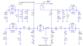
The circuit I used is in the attached graphic. It's meant to evaluate the effects of the output inductor. The same simulated speaker is driven from an ideal zero impedance source and a source with a parallel 6 uH, 8.2 Ohm RL network in series with it. The difference voltage across the two tweeters is captured to a WAV file. First, I captured the input to a WAV file and verified that I got a good quality replica of the original sound. The original was a mono-converted version of the song "Almost Gothic" from the Steely Dan "Two Against Nature" album. Then I switched over to capturing the tweeter error voltage to the WAV file. I only simulated the first 20 seconds of the song, as the simulation is much slower than real-time.
The result? Well maybe I'm deaf, but all I could hear was total silence. This is changing my view of the output inductor.
I've performed the difference test using WAV file input and output. I'm still unable to get my Squeezebox 2 to play the LTSpice WAV output files. The problem appears to be two zero byte counts in the WAV header which I'll write some code to fix up later. However, foobar plays these files just fine and this allows me to hook up the Sennheiser 580 headphones directly to the analog out of my E-MU 1212m sound card to play them. So that's what I did. I'm able to play music loud enough with this setup to be uncomfortable.
The circuit I used is in the attached graphic. It's meant to evaluate the effects of the output inductor. The same simulated speaker is driven from an ideal zero impedance source and a source with a parallel 6 uH, 8.2 Ohm RL network in series with it. The difference voltage across the two tweeters is captured to a WAV file. First, I captured the input to a WAV file and verified that I got a good quality replica of the original sound. The original was a mono-converted version of the song "Almost Gothic" from the Steely Dan "Two Against Nature" album. Then I switched over to capturing the tweeter error voltage to the WAV file. I only simulated the first 20 seconds of the song, as the simulation is much slower than real-time.
The result? Well maybe I'm deaf, but all I could hear was total silence. This is changing my view of the output inductor.
Attachments
andy_c said:I thought the effect of a right shift was implementation-defined when the integers are signed?
Oops, I wan't thinking here. What happens to the MS bit of the 32-bit long in the right shift is irrelevant, since the 16 MS bits get chopped off in the conversion to 16-bit integer anyway.
Hello, Andy
Once you rond off the SW and models, this will be a VERY interesting test!
Cheers!
Jorge
Once you rond off the SW and models, this will be a VERY interesting test!
Cheers!
Jorge
Hi Andy !
You are right with the rightshift on signed values, -1 shifted right keeps
-1, but divided by 2 gives 0... But this is correct and the reason for
the +1 in my formula.
In graphics you have to do this symetric rounding, otherwise you
would have to divide by 255 instead of >>8...
Integer arithmetic is the only reliable one, very different to this float-crab...
I already tried to simulate bandwidthlimited feedbackloops with
dsp-programming, but all i could proove is that feedback cancels
all errors if applied enough... I failed with the wish to simulate
bad sounding amps...
Hopefully you get more results !
Mike
MikeB said:You are right with the rightshift on signed values, -1 shifted right keeps
-1, but divided by 2 gives 0... But this is correct and the reason for
the +1 in my formula.
Hmmm, I'm going to have to think some more about what you're saying before it all sinks in. As you can tell, I'm not a DSP guy 🙂.
- Status
- Not open for further replies.
- Home
- Amplifiers
- Solid State
- The many faces of distortion