Don't you think that the sound engineer that created that two channel audio would have evaluated the dimensional/holographic presentation of that recording using 2 speakers that also have the same stereo cross talk. In other words a good stereo recording would have been compensated already for that cross talk?
Again after experiment no. 1011 or so, I'd just want to say: why don't you try it yourself? With a PC as source it is easy enough to just setup and try it.
As said, I've tried at least 4 different ways (more actually, not all equally successful) and had a great time trying it. The mid/side EQ is probably the easiest to get working. In this thread I've shown measurements of what happens at "my ear position". The Phantom Center thread has clear plots from jim1961 in his excellent room. This stuff is real.
Oh no! Not another experiment! Triggered by the many simulations fron nc535 I decided to jump aboard. However my target is a little different from nc535.
I'm not looking to avoid combing completely, I want to keep the current positives of 'seemingly' unchanged sound over a wide listening area.
https://www.diyaudio.com/forums/full-range/337956-range-line-array-wall-corner-placement-54.html#post6204985
Seems worth it though, to at least try it. I'm only interested in simple to implement passive solutions.
Not planning to put aside the reference amplifier I have. But if an advancement is to be had, I'm all for it.
It would probably be a vacation time project. As my living room will undergo a slight renovation, that would be a good time to
go into the garage and whip up some changes. I still need to check my impedance compensation and this circuit.
X-sim says it will work alright.
Last edited:
I've been playing with Virtuixcad non stop for a few days. I'll copy the results from the thread I linked to a couple of posts ago to keep it within my own thread, as it is my arrays that are simmed here:
Here's a comparison at the listening spot for a frequency shelf-shaded array vs unshaded:
The upper results are the shelf-shaded array, bottom is the unshaded array.
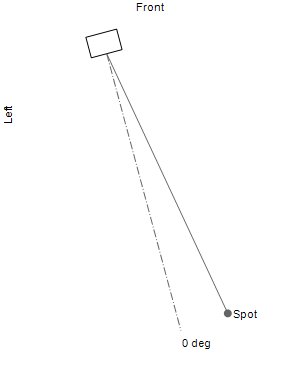
These are the in-room results of positions between -100 to +100mm around the 1000 mm height measurement spot. I'd say it looks to be worth the trouble. The results of the 15 degree array toe-in and 10 degree off axis listening is much more in line with what I had expected.
The results are more even than the prior angle I used (on axis sims). Pretty much in line with my toe-in experience a long long time ago. The 10 degree off axis was my subjectively preferred listening angle, having the array cross behind the listening spot. (or in front but due to how strange that looked I did not dare let that pass judgement on the WAF front)
Edit: these simulations keep a reasonable tonal balance up to 1700 mm. That's the rule number one: it should work standing up.
A by-product of the shaded array is much better tonal performance standing up and at 4 m distance. So room sound could improve too.
Belonging to the above graph, comparing shaded vs unshaded the 6-pack from Virtuixcad:
The in-room results were averaged and used for EQ correction in both plots.
So to recap:
I applied a pré-eq to get a somewhat flat result. Next I exported the Listen win SPL, which I altered in value to see a window of +/- 15 degree horizontal and +/- 5 degree vertical.
The listen-win IR was then corrected by DRC-FIR. The result of that was convolved with the pré-EQ to get a total correction.
This total correction was applied within Virtuixcad to the sim. Next I exported the in-room results looking at the height-differences from -100, -75, -50, -25, 0, 25, 50, 75 up to 100.
These results were averaged (non vector) and I let REW do auto EQ on that result, with a few quick tweaks. That EQ was applied to all measurements and the correction as seen in the upper six-pack(s).
Same procedure for both sims, Shaded and Unshaded.
Lots of work, but I need to find out if operating on the arrays is worth the trouble.
In the shaded version I've included my impedance correction schematic.
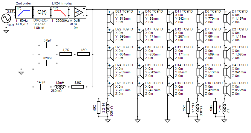
It is what I run, so I included it in the sim.
The above is with the earlier mentioned toe-in:
Cross-link: https://www.diyaudio.com/forums/full-range/337956-range-line-array-wall-corner-placement-60.html#post6209895
Here's a comparison at the listening spot for a frequency shelf-shaded array vs unshaded:
The upper results are the shelf-shaded array, bottom is the unshaded array.
These are the in-room results of positions between -100 to +100mm around the 1000 mm height measurement spot. I'd say it looks to be worth the trouble. The results of the 15 degree array toe-in and 10 degree off axis listening is much more in line with what I had expected.
The results are more even than the prior angle I used (on axis sims). Pretty much in line with my toe-in experience a long long time ago. The 10 degree off axis was my subjectively preferred listening angle, having the array cross behind the listening spot. (or in front but due to how strange that looked I did not dare let that pass judgement on the WAF front)
Edit: these simulations keep a reasonable tonal balance up to 1700 mm. That's the rule number one: it should work standing up.
A by-product of the shaded array is much better tonal performance standing up and at 4 m distance. So room sound could improve too.
Belonging to the above graph, comparing shaded vs unshaded the 6-pack from Virtuixcad:
The in-room results were averaged and used for EQ correction in both plots.
So to recap:
I applied a pré-eq to get a somewhat flat result. Next I exported the Listen win SPL, which I altered in value to see a window of +/- 15 degree horizontal and +/- 5 degree vertical.
The listen-win IR was then corrected by DRC-FIR. The result of that was convolved with the pré-EQ to get a total correction.
This total correction was applied within Virtuixcad to the sim. Next I exported the in-room results looking at the height-differences from -100, -75, -50, -25, 0, 25, 50, 75 up to 100.
These results were averaged (non vector) and I let REW do auto EQ on that result, with a few quick tweaks. That EQ was applied to all measurements and the correction as seen in the upper six-pack(s).
Same procedure for both sims, Shaded and Unshaded.
Lots of work, but I need to find out if operating on the arrays is worth the trouble.
In the shaded version I've included my impedance correction schematic.
It is what I run, so I included it in the sim.
The above is with the earlier mentioned toe-in:
Cross-link: https://www.diyaudio.com/forums/full-range/337956-range-line-array-wall-corner-placement-60.html#post6209895
The chart I have not shown yet are the sitting/standing comparisons.
I've used psychoacoustic smoothing on these in-room results, as neither graph, be it unshaded or shaded, provides excellent results. Looking for balance here:
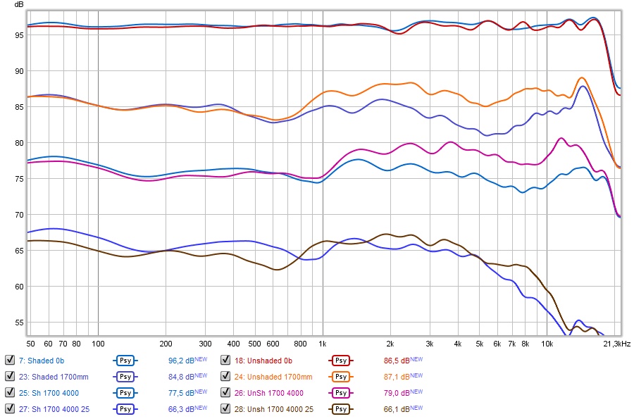
Obviously the shaded array will sound darker, while the unshaded array will sound a little brighter when standing up. Both show a maximum deviation of 5 dB between 100 Hz and 10 KHz.
This was the biggest compromise that I was willing to make. Neither is perfect, but I think it still is an acceptable compromise for the overall gain you get at seated listening positions.
At a distance of 4 meter the shaded array is showing a more even response while the unshaded version remains bright. However at a more distinct angle
the unshaded array will have an advantage in extension.
(under this specific angle of 25 degree, at 4 meter distance, the shaded version looks like an almost perfect 12 dB/octave roll off at 6 KHz)
The 1700 mm height was chosen because my ear is at that level standing up 😉.
P.S. I just tried to mimic the above results with headphones and graphic EQ. I do believe I could live with this compromise.
I've used psychoacoustic smoothing on these in-room results, as neither graph, be it unshaded or shaded, provides excellent results. Looking for balance here:
Obviously the shaded array will sound darker, while the unshaded array will sound a little brighter when standing up. Both show a maximum deviation of 5 dB between 100 Hz and 10 KHz.
This was the biggest compromise that I was willing to make. Neither is perfect, but I think it still is an acceptable compromise for the overall gain you get at seated listening positions.
At a distance of 4 meter the shaded array is showing a more even response while the unshaded version remains bright. However at a more distinct angle
the unshaded array will have an advantage in extension.
(under this specific angle of 25 degree, at 4 meter distance, the shaded version looks like an almost perfect 12 dB/octave roll off at 6 KHz)
The 1700 mm height was chosen because my ear is at that level standing up 😉.
P.S. I just tried to mimic the above results with headphones and graphic EQ. I do believe I could live with this compromise.
Last edited:
More sim work done, more results, not entirely happy yet. I was able to improve upon the results above with a slight difference in my shelf shading. As the impedance of the TC9 rises in the upper frequencies, the shelf shading isn't quite as effective there. With an extra inductor inline we can remedy that.
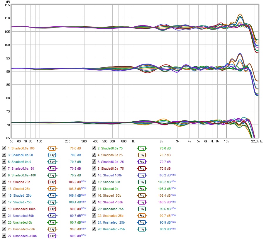
This seemed to clear up the top end even further:
Top one is the earlier shelf shaded example (shown before on this thread), middle one is the unshaded array and the bottom one is my new suggestion, the one with extra inductors to shade the top end.
It is easy to see, as these are raw in-room results, the differences. Based on this graph alone, I'd pick the bottom graph as a clear winner. It has less variation, similar processing on all graphs, including floor and ceiling reflections.
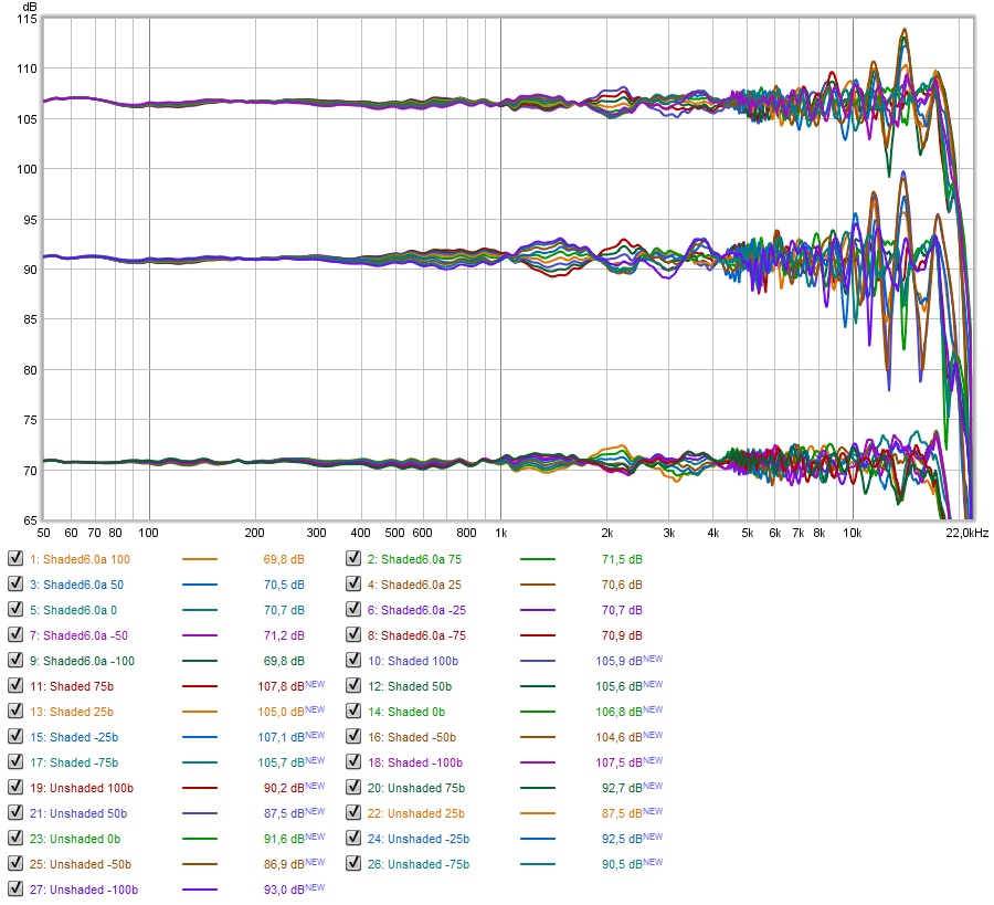
But let's examine it a bit closer. If I show the same graphs with psycho-acoustic shading we get a slightly different picture:
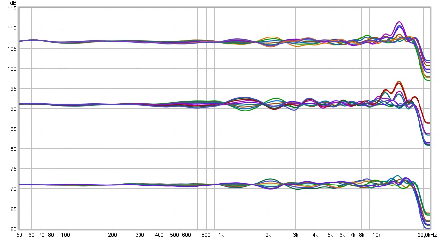
Even though the unshaded array has the biggest wiggles, we might state that it does keep a good balance at each position. Something I'd agree on as that is how I perceive my array. It shows great bundling of these results. While there are lots of wiggles, they are averaging out on a similar balance.
Now we see that the shaded examples improve on the top end, especially my new found shading logic. However the balance does show more variation.
Another look, this time with 1/3 octave smoothing:
Because I'm not in the middle of the array, you see that the bundling after this smoothing is less ideal than that of an unshaded array. It will take more time/work to try and find further improvements.
I'd like to get close to the bundling of an unshaded array, while keeping the upper advantage, less wiggles. I do think it should be possible. As stated before on the simulation thread, I'm not looking for a complete wiggle free solution, as it will be very hard to keep that, while adding natural floor and ceiling reflections. Plus I don't think that is the complete secret to success.
Part of what makes the array principle work for me is how I can get away with less treatment overall and still have/get awesome results. Yes I've treated first reflection points, but not much else.
The multiple drivers allow me to get away with that, nothing else. It averages out a lot of strong reflections (every driver being at a different position with slightly different reflection properties) compared to a setup with a single driver. Unless you'd have room for big waveguides or horn type speakers it will be hard to avoid this. I still get a high level of direct sound compared to the reflected sound and can negate the influence of floor and ceiling reflections without treatment on those surfaces, giving me a clear look into every song much like being there.
What I robbed from the room in the form of the damping/absorbing of first reflections I make up for with the ambient channels. Making it possible to get a neutral tonal balance over a wide area and still have great imaging. These were the main points for me to go with arrays.
So I'll be on the sim wagon a little longer to see if I can have my cake and eat it too! 🙂
I'm getting a little closer and believe it should be possible to find a combination of components that works well, out there in a real room.
Once again, I'm not looking to rid myself of all wiggles, just reduce them enough so the perceived balance remains. I'll gladly consider adding a few wiggles of my own (and have done so) to improve the Stereo illusion. That's what the mid/side EQ and cross talk experiments were all about.
I'm positive some tweaks here might help, but I do need to have them work over a similar wide area than the unshaded arrays before biting the bullet and trying it for real.
This seemed to clear up the top end even further:
Top one is the earlier shelf shaded example (shown before on this thread), middle one is the unshaded array and the bottom one is my new suggestion, the one with extra inductors to shade the top end.
It is easy to see, as these are raw in-room results, the differences. Based on this graph alone, I'd pick the bottom graph as a clear winner. It has less variation, similar processing on all graphs, including floor and ceiling reflections.
But let's examine it a bit closer. If I show the same graphs with psycho-acoustic shading we get a slightly different picture:
Even though the unshaded array has the biggest wiggles, we might state that it does keep a good balance at each position. Something I'd agree on as that is how I perceive my array. It shows great bundling of these results. While there are lots of wiggles, they are averaging out on a similar balance.
Now we see that the shaded examples improve on the top end, especially my new found shading logic. However the balance does show more variation.
Another look, this time with 1/3 octave smoothing:
Because I'm not in the middle of the array, you see that the bundling after this smoothing is less ideal than that of an unshaded array. It will take more time/work to try and find further improvements.
I'd like to get close to the bundling of an unshaded array, while keeping the upper advantage, less wiggles. I do think it should be possible. As stated before on the simulation thread, I'm not looking for a complete wiggle free solution, as it will be very hard to keep that, while adding natural floor and ceiling reflections. Plus I don't think that is the complete secret to success.
Part of what makes the array principle work for me is how I can get away with less treatment overall and still have/get awesome results. Yes I've treated first reflection points, but not much else.
The multiple drivers allow me to get away with that, nothing else. It averages out a lot of strong reflections (every driver being at a different position with slightly different reflection properties) compared to a setup with a single driver. Unless you'd have room for big waveguides or horn type speakers it will be hard to avoid this. I still get a high level of direct sound compared to the reflected sound and can negate the influence of floor and ceiling reflections without treatment on those surfaces, giving me a clear look into every song much like being there.
What I robbed from the room in the form of the damping/absorbing of first reflections I make up for with the ambient channels. Making it possible to get a neutral tonal balance over a wide area and still have great imaging. These were the main points for me to go with arrays.
So I'll be on the sim wagon a little longer to see if I can have my cake and eat it too! 🙂
I'm getting a little closer and believe it should be possible to find a combination of components that works well, out there in a real room.
Once again, I'm not looking to rid myself of all wiggles, just reduce them enough so the perceived balance remains. I'll gladly consider adding a few wiggles of my own (and have done so) to improve the Stereo illusion. That's what the mid/side EQ and cross talk experiments were all about.
I'm positive some tweaks here might help, but I do need to have them work over a similar wide area than the unshaded arrays before biting the bullet and trying it for real.
Attachments

As nc535 did back on his thread, I'd gladly invite others to join the fun of finding these answers. There's enough of us TC9 array users around that could possibly benefit from this, if it turns out to be an overall improvement.
The sims cost nothing but time. But that in itself is hard enough to find sometimes 😀.
On a completely different subject: I'll have more electronics to play with sometime soon! 3 Universal buffers are on their way to me.... 🙂
The sims cost nothing but time. But that in itself is hard enough to find sometimes 😀.
On a completely different subject: I'll have more electronics to play with sometime soon! 3 Universal buffers are on their way to me.... 🙂
I'm trying to get to grips with ABEC at the moment so the black hole of VituixCad will have to wait for me. You and nc535 are doing an awesome job anyway 😉
My wiring is divided into 5 driver sections with wago wire clamps so testing out the sort of passive shading you are describing here wouldn't be physically that difficult from what I can see.
My wiring is divided into 5 driver sections with wago wire clamps so testing out the sort of passive shading you are describing here wouldn't be physically that difficult from what I can see.
ABEC - talk about a black hole and one with long processing times. I've tried to do that several times but have always been distracted by something else, like Vituix that yields results more quickly, but not for the same problems.
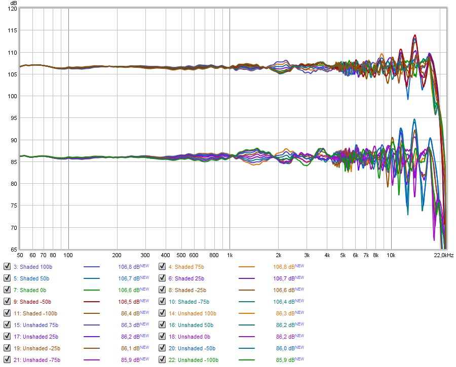
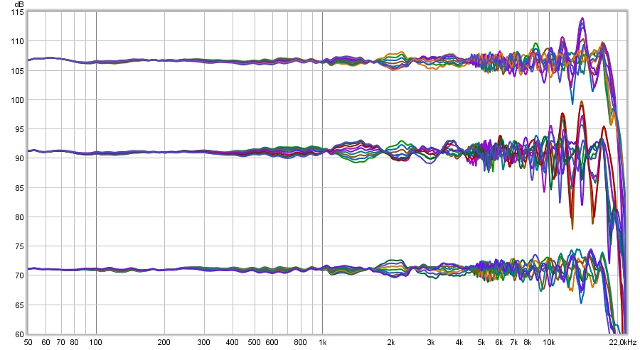
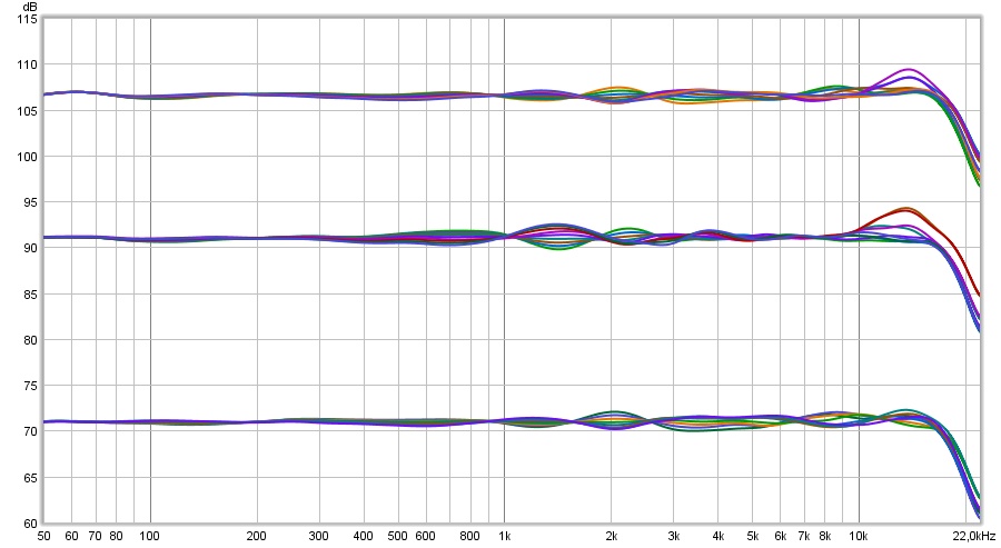
The next step:
Top graph is the first shelf shaded attempt as seen before,
Center is unshaded
Bottom is the new shelf shading with top end compensation.
Still passive filters only, shelf shaded plus inductor top end compensation. I sort of cheated, but it's very doable in wiring. I made the center group of 5 drivers unshaded and centered around my desired 1 meter listening height. The group right around that is 3 drivers below that center group and two drivers above it, so I could more easily shade their (very) top end.
The rest is back to normal as groups of 5 drivers, but I needed that tweak to get more bundling of the drivers around the center axis. I think I did quite OK. Maybe there's more to be had, as always.
Heights span +100 to -100 around the listening axis of 1 meter, in 25 mm steps.
The results without smoothing:
I'd say a clear difference 🙂. I think even the raw results look pretty awesome with the exact same settings used to make all three graphs.
Normalised comparison between unshaded and shaded 6.0...
As the boost on the upper end for the group of 5 drivers is no higher than it was for the unshaded array, I'd say that this should be save to implement without worrying.
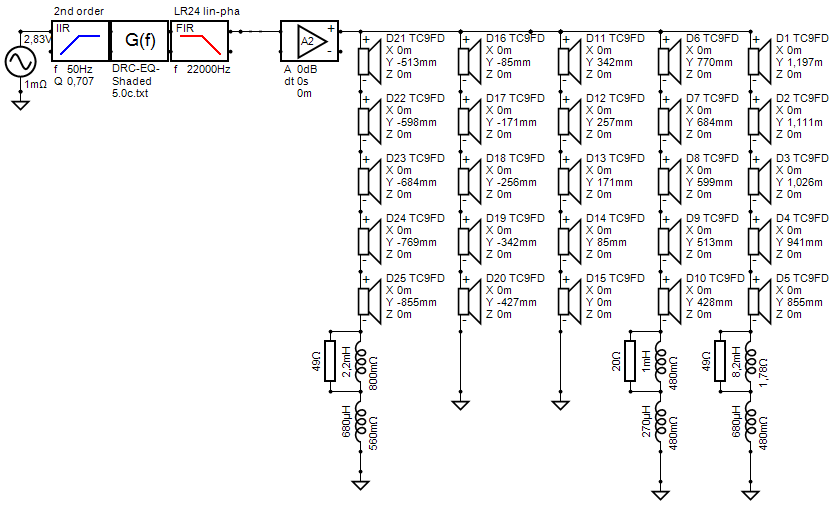
The shading schematic I used:
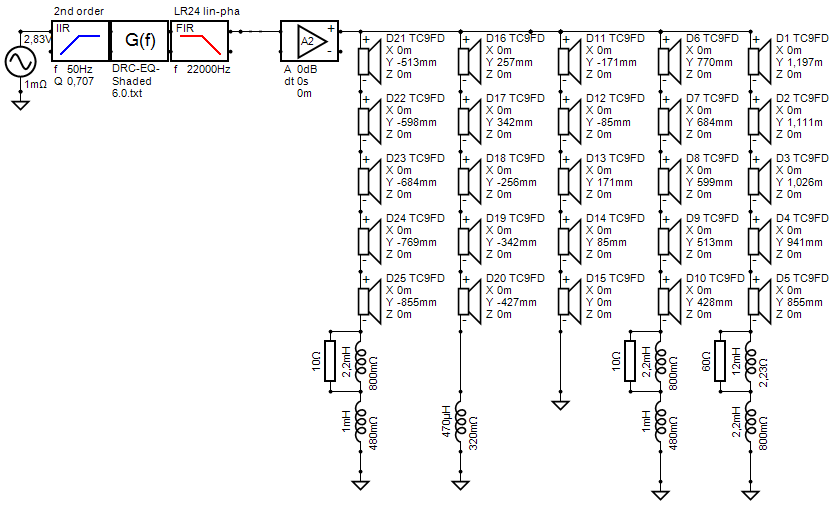
(look at the height numbers to see how I grouped the drivers)
To make this set complete, I've included the 1.70 meter standing height of both the unshaded and shaded array:
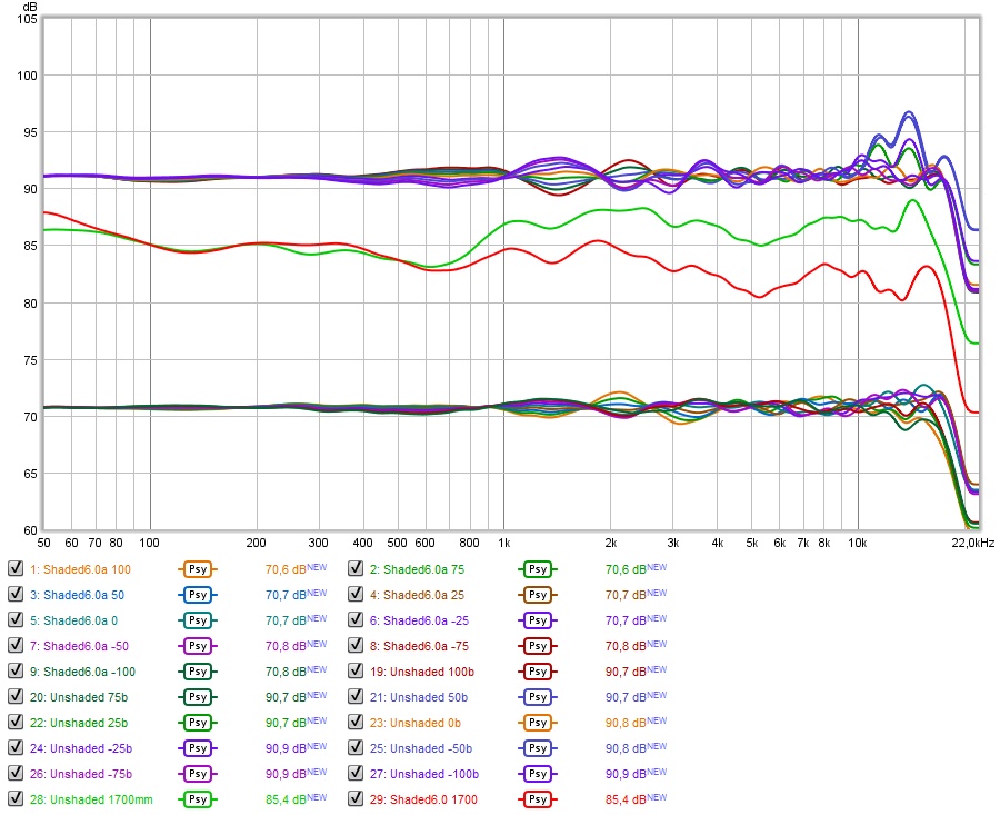
The unshaded array (green) is a little bright standing up. I guess I'd have to trade that in for a little darker (red) if I go ahead with shading...
I'm pretty sure I could live with that...
As long as I'm feeling a little victorious about this improvement, here's the predicted IR & Step (from Vituixcad)*
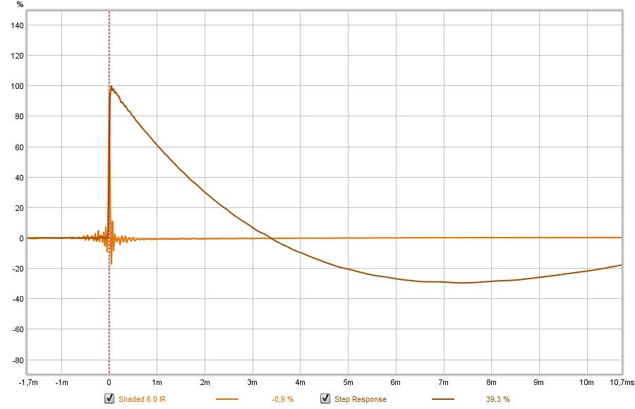
*= second time I spelled it right I think 😀
Top graph is the first shelf shaded attempt as seen before,
Center is unshaded
Bottom is the new shelf shading with top end compensation.
Still passive filters only, shelf shaded plus inductor top end compensation. I sort of cheated, but it's very doable in wiring. I made the center group of 5 drivers unshaded and centered around my desired 1 meter listening height. The group right around that is 3 drivers below that center group and two drivers above it, so I could more easily shade their (very) top end.
The rest is back to normal as groups of 5 drivers, but I needed that tweak to get more bundling of the drivers around the center axis. I think I did quite OK. Maybe there's more to be had, as always.
Heights span +100 to -100 around the listening axis of 1 meter, in 25 mm steps.
The results without smoothing:
I'd say a clear difference 🙂. I think even the raw results look pretty awesome with the exact same settings used to make all three graphs.
Normalised comparison between unshaded and shaded 6.0...
As the boost on the upper end for the group of 5 drivers is no higher than it was for the unshaded array, I'd say that this should be save to implement without worrying.
The shading schematic I used:
(look at the height numbers to see how I grouped the drivers)
To make this set complete, I've included the 1.70 meter standing height of both the unshaded and shaded array:
The unshaded array (green) is a little bright standing up. I guess I'd have to trade that in for a little darker (red) if I go ahead with shading...
I'm pretty sure I could live with that...
As long as I'm feeling a little victorious about this improvement, here's the predicted IR & Step (from Vituixcad)*
*= second time I spelled it right I think 😀
Good work on the spelling but now you have gone and made it so your shading won't work with my wiring scheme and inside cabinet structures so if I do try anything it will have to be different.*= second time I spelled it right I think 😀
If you can still reach the drivers, one might get very close with a caps on the outer (2 and 3) drivers of the middle groups without rewiring...
So what do you think about the results?
So what do you think about the results?
I wasn't paying attention at first to the height of the drivers in the 5 groups in series I thought they were as they come rather than being rearranged, maybe they were before?
Anyway in my cabinet the 5 series drivers are in their own sealed space with the main backbone wire going through each but sealed as well. This means that I can do anything simple within those five spaces but joining individual drivers across them will involve drilling holes and messing about that I am not prepared to do. It would almost make sense to go with a Mark II cabinet for the effort involved.
Because of those separate enclosures I have a handy shelf to sit components on and the wiring is all quick connects and wago joints so adding them in isn't much effort beyond a couple of wires and removing a few drivers.
I think for the cost of the components it is worth trying because for all the simulations in the world we won't know until someone gives it a go. Correcting the comb pattern in the high frequencies does sound better to me in my listening position but it no doubt makes things worse elsewhere so I do think there is merit in anything that can tame that and not lose all the good qualities that I built the array for in the first place.
I don't listen standing up and if I did I would probably not be so critical so that part doesn't worry me and I would have to go higher than 1700mm in any case 🙂
What's your ceiling height? The sims I do are based upon my ceiling height after i finish up my living room renovation. Only in the "shaded 6.0" has the rearranged the driver groups.
Your specific listening height will matter as well. Due to my ceiling at 2.92 meter (after the renovation) I'm not able to get the symmetry I was looking for. So in your case thing 'might' just work ok with a simpler schematic without rearranging driver pools.
I noticed going above my desired 1 meter listening height had worse results than dropping below it. I figured it was worth a shot to regroup the drivers to see if better results could be had if I did.
Within the sim we have a fixed value for absorption for both ceiling and floor. No way of knowing what that absorption value is in real life. I just compare the unshaded to the shaded sims while looking for trends.
I'll probably run a few more sims to learn from it before biting the bullet and make a decision. But the odds are in favor of trying the frequency shading.
I did make my cabinets serviceable for a reason 😉.
Anyway, caps parralel to separate drivers could mimic what I do with rearranging driver groups I guess. More ways to skin a cat...
Last edited:
My Ceiling height is 2.7m and listening height would be about the same at 1m.
Each separate enclosure is very serviceable for me but not from one to another, would be easier to drill holes through the back and run the wires on the outside but I'm not going to do that either 🙂
Each separate enclosure is very serviceable for me but not from one to another, would be easier to drill holes through the back and run the wires on the outside but I'm not going to do that either 🙂
Anyway, caps paralel to separate drivers could mimic what I do with rearranging driver groups I guess. More ways to skin a cat...
No such luck, the caps change the balance of the rest of the drivers in a group.
Well I will do whatever it takes if it actually boosts the performance 😀.
But no way of knowing until we try, I guess.
As there will be a time frame where my speakers have to leave the room, I could operate on them... it will all be reversible anyway.
But no way of knowing until we try, I guess.
As there will be a time frame where my speakers have to leave the room, I could operate on them... it will all be reversible anyway.
If you don't listen standing up, then you can be more agressive than Wesayso in your shading. The more you cut off the highs of the more distant drivers the more you reduce the combing at ear level. That is why I have a second low pass filter slope on my two outer shelves. The first shelf filter gets down to the horizontal shelf amplitude and the 2nd cuts off the highs where they are no longer needed to support the central drivers in the midrange. This does affect the response elsewhere than near ear level but the primary effect is the lack of treble at the levels of the shaded drivers.I don't listen standing up
Incredible body of work here. It’s an amazing time for Line Array enthusiasts with this, Jim Griffith’s work and Don’s CBT......something for everyone. As AI becomes more consumer oriented, it will be interesting to see what DIYers can develop.
Always a little shocked that after more than a century, the dynamic driver is still the prevelant source in the audio world. If it ain’t broke.........
Always a little shocked that after more than a century, the dynamic driver is still the prevelant source in the audio world. If it ain’t broke.........
- Home
- Loudspeakers
- Full Range
- The making of: The Two Towers (a 25 driver Full Range line array)