Thanks mayhem13,
We do try 🙂. I have to thank Jack (nc535) for the motivation to try sims like these and of course Kimmo (kimmosto) for a marvelous tool in the form of Vituixcad that can simulate all of this.
Even before I started building the arrays (and extensive research done on the papers from Jim Griffith and Don Keele) I've always wondered what a frequency dependent shading could bring to straight arrays like the one I was planning. It did feel like a viable option to keep the dynamic nature of the unshaded arrays compared to more straight forward shading schemes which loses a lot of SPL potential in the bottom end.
It would have been rather difficult to predict or come up with a good schematic. Something the power of Vituixcad now brings to us DIY crowd to play with. I'm glad we can continuously try and bend the limits to possibly gain performance. These tools help a lot! Not forgetting Mr. Waslo with X-Sim and many many more. I think if we work together, as a DIY group we can push the limits and have a lot of fun in the process. It is working better and better everywhere on the forum.
Last edited:
I'm constantly posting my progression in two threads, maybe I'll just post here, as nc535 is busy finding the right values for his array featuring different drivers (even in size).
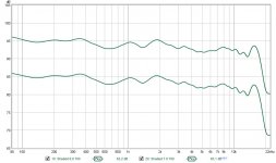
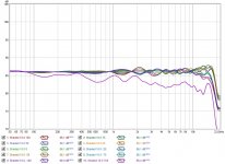
I was looking for an upgrade of standing performance, hoping I'd get it without any big compromises. I think I've managed to achieve it:
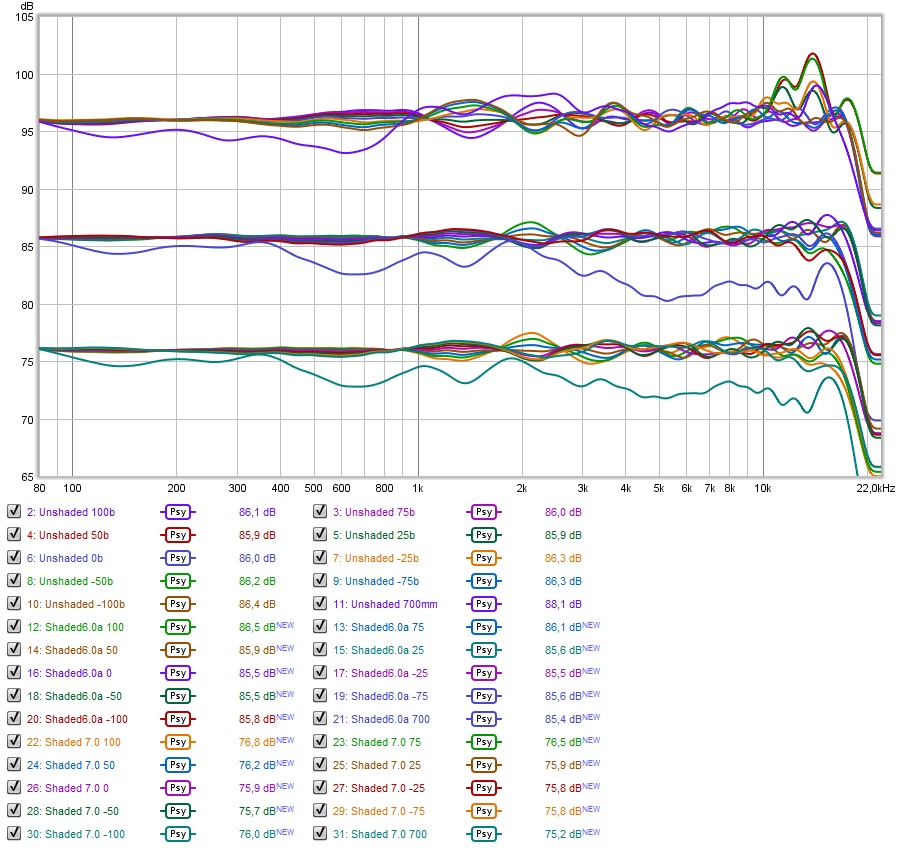
Top - Unshaded (as seen before)
Middle - Shaded 6.0 (seen previously, using shelf shading + top end compensation)
Bottom - Shaded 7.0 (new variation with the task of better standing, 1.7 meter, performance)
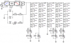
I've tried many things, in the end it was quite simple. I just had to learn about passive compensation filters like notches etc. Here's the schematic:
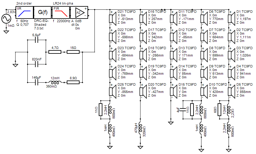
All it took was an extra cap and a slight change in component values. I may yet find ways towards further improvements. But most of it is within plus/minus 1 dB from 900 cm to 1100 cm.
The difference in the 5 KHz dip is almost 1.5 dB in favor of this last schematic. Not bad for a passively filtered frequency dependent solution I'd say.
It is getting closer and closer to an 'upgrade solution' without many drawbacks. Let's see if i can find even more subtle improvements.
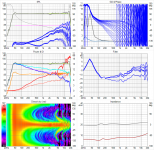
I'll post the Vituixcad 6-pack, however there's almost no difference to version 6.0 unless you're pixel peeping:

(aside from the extra split in processing groups)
I was looking for an upgrade of standing performance, hoping I'd get it without any big compromises. I think I've managed to achieve it:
Top - Unshaded (as seen before)
Middle - Shaded 6.0 (seen previously, using shelf shading + top end compensation)
Bottom - Shaded 7.0 (new variation with the task of better standing, 1.7 meter, performance)
I've tried many things, in the end it was quite simple. I just had to learn about passive compensation filters like notches etc. Here's the schematic:
All it took was an extra cap and a slight change in component values. I may yet find ways towards further improvements. But most of it is within plus/minus 1 dB from 900 cm to 1100 cm.
The difference in the 5 KHz dip is almost 1.5 dB in favor of this last schematic. Not bad for a passively filtered frequency dependent solution I'd say.
It is getting closer and closer to an 'upgrade solution' without many drawbacks. Let's see if i can find even more subtle improvements.
I'll post the Vituixcad 6-pack, however there's almost no difference to version 6.0 unless you're pixel peeping:
(aside from the extra split in processing groups)
Attachments
Last edited:
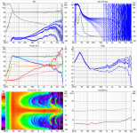
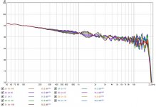
I'm still throwing out sims like crazy. How much is good enough? I'm approaching plus/minus 2 dB variation all the way up to 10 KHz (unsmoothed).
Side note: there is absorption on floor and ceiling, as those become the biggest sources of combing. Same value used for all these and previous sims.

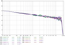
The last improvements let go of some of the standing ideal... Less than one dB drop on the upper end though. Almost a steady decline along the whole graph.

Let's look at the 20 cm 'vertical window' results when filtered:

Looking at it like that almost makes it fit a plus/minus 1 dB window.
New schematic:

And related 6-pack:

The difference in filter 7.0 vs 8.0:

Now if only I could figure out what I need to do to make the 1 Khz to 4 KHz a little more balanced. I did try a few things, but no bingo yet. The horizontal pattern shows a narrowing there so that might be related. It might even behave differently with my back mounted drivers.
It is performing better than the unshaded array though. So it's only the challenge that counts. 🙂
Anyone any ideas of things to try to achieve this?
Side note: there is absorption on floor and ceiling, as those become the biggest sources of combing. Same value used for all these and previous sims.
The last improvements let go of some of the standing ideal... Less than one dB drop on the upper end though. Almost a steady decline along the whole graph.
Let's look at the 20 cm 'vertical window' results when filtered:
Looking at it like that almost makes it fit a plus/minus 1 dB window.
New schematic:
And related 6-pack:
The difference in filter 7.0 vs 8.0:
Now if only I could figure out what I need to do to make the 1 Khz to 4 KHz a little more balanced. I did try a few things, but no bingo yet. The horizontal pattern shows a narrowing there so that might be related. It might even behave differently with my back mounted drivers.
It is performing better than the unshaded array though. So it's only the challenge that counts. 🙂
Anyone any ideas of things to try to achieve this?
Attachments
-
 compare 7.0 vs 8.0.jpg164.8 KB · Views: 360
 -
 compare 7.0 vs 8.0 standing.jpg84.8 KB · Views: 342
 -
 Compare 7.0 vs 8.0 psy.jpg156.7 KB · Views: 336
 -
 25x TC9 FR Shaded 8.0 Six-pack.png307 KB · Views: 331
 -
 25x TC9 FR Shaded 8.0 XO-schema.png33.8 KB · Views: 348
 -
 Differenceinfilter.gif12.7 KB · Views: 385
Last edited:
One thing to notice in these little upgrades is that the correction is approaching a flatter curve. This last one has a dB less of boost on the top end and less wiggles overall.
I don't run multiple convolvers in JRiver. If I do need that, I convolve the two FIR filters together within REW using the (A * B) algorithm. For instance if I want to make phase tweaks with RePhase, I convolve my DRC FIR filter with that phase tweak and level match the resulting filter, as (A * B) will generally result in an SPL rise if the filter isn't SPL neutral.
I use that same trick in these sims as well. Just like Jack (nc535) I first make a correction for the desired listening window. Then export all heights I want to investigate into REW, and average those results (no vector average). I then EQ the average results to a straight line.(*)
I then export the EQ to an impulse, drop the SPL level to zero on average and convolve all height measurements with the EQ.
(*)= I do the EQ myself as that gives better results than running automated. I have had lots of practise with EQ-ing so it all goes pretty quick.
Last edited:
Ah more caps!
1-4 khz region? I would try boosting the most distant group a few db in that range without affecting its level above that range. That could be done with a series, lowQ RLC across the resistor that sets the shelf level but I would try it active to see if it worked before calculating component values. That suggestion comes not from insight so much as not seeing anything else to try that wouldn't hurt elsewhere.
1-4 khz region? I would try boosting the most distant group a few db in that range without affecting its level above that range. That could be done with a series, lowQ RLC across the resistor that sets the shelf level but I would try it active to see if it worked before calculating component values. That suggestion comes not from insight so much as not seeing anything else to try that wouldn't hurt elsewhere.
It turns out I need to reduce the output on the outer driver groups. Not that easy with passive components without messing it up at other frequencies, comparison linked at the bottom of the post.
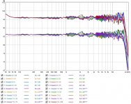
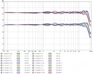
I lost some of the bundling higher up the chain, but we're talking peanuts. Maybe I should do a comparison to the unshaded and both shaded variants. Here we go:

🙂
Let's see the raw results as well...

This will be it for a while.... More to fine tune no doubt, less time in the coming days.
Can anyone pick the one that will sound better? 😱
I lost some of the bundling higher up the chain, but we're talking peanuts. Maybe I should do a comparison to the unshaded and both shaded variants. Here we go:
🙂
Let's see the raw results as well...
This will be it for a while.... More to fine tune no doubt, less time in the coming days.
Can anyone pick the one that will sound better? 😱
Attachments
A box of electronics just arrived from Canada. 3x Universal Buffer and a Power supply. 🙂
Now to find the time and the rest of the parts to build a fixed gain (3 settings) 6 channel pré-amp.
Now to find the time and the rest of the parts to build a fixed gain (3 settings) 6 channel pré-amp.
Perhaps a longer answer than needed, but over time I did feel there's a sweet spot for digital gain / DAC that favored using a pré amplified signal for my listening pleasure. That's how I ran the Pioneer amplifier i was using before.
By having adjustable, but fixed gain I can cater all listening scenario's I can think of. I noticed that the Goldmund amp sounded great at lower SPL levels than I ever managed to squeeze out of the Pioneer. Yet at higher SPL levels adding a pré amplifier won me over.
So having 3 switches (one for ever Universal buffer) with 3 gain positions should suit my taste. I've talked it over with Tom and he suggested the switches to me. It's what he had in his HP-1 headphone amplifier which we have used as a Pré-amp while testing the different amplifiers. The Goldmund, the Fetzilla, the Roender FC100 and the My Ref Fremen edition. That story is documented here: https://www.diyaudio.com/forums/full-range/242171-towers-25-driver-range-line-array-411.html#post5353321
BYRTT brought that HP-1 for some other tests, but we ended up using it as a pré-amp. Only after buying an JDS Atom amplifier for similar duty was I able to get back the sound I loved dearly. The Atom pré was a simple proof of concept test, BYRTT suggested it to me, for a spin.
I hope to get that same feel back by making a 6 channel pré-amp, still deciding on the gain setting I'd need.
Buying a couple of resistors and switches is cheaper than my original plan, a 6 channel analog volume control. So for starters I think the adjustable gain, together with some digital volume fine tuning will serve me well. I can do background music, Home Theatre movies at ~75 dB average and rock out with music at even higher levels, while using the DAC / digital circuit in its sweet spot.
The pré will not be in the room with me, so a full blown volume pot won't do me any service there. But I do recognise the limits of digital volume control, once you use up the sort of range I do with EQ needs for these arrays.
It will, over time, make me ready to go all balanced with my long cables from the PC to the amplifiers. I'll start with the subwoofers, that were meant to be balanced anyway. Then, over time I may add buffers to the Goldmund and Fetzilla (when the budget allows).
Last edited:
These buffer boards are tiny! I guess the case will be determined by all the connections I need. 6x RCA in + 6x Differential in and 6x RCA out + 6x Differential out.
That will give me all options I need and flexibility to try whatever I fancy.
That will give me all options I need and flexibility to try whatever I fancy.
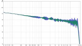
I couldn't stop simming completely, here's version 10 of the frequency shaded array:

And to look at the results before the floor and ceiling were added:

This last results is based on the raw in-room measurements, EQ-ed to make the average flat (declining 1 dB per octave)
Once I have more time, i'll see what that does for the unshaded array. Just to see if the shaded array is less sensitive to room influence. My hunch is the unshaded array needs some room to look good (after applying a psycoacoustic filter).
The above result does look promising to me...
And to look at the results before the floor and ceiling were added:
This last results is based on the raw in-room measurements, EQ-ed to make the average flat (declining 1 dB per octave)
Once I have more time, i'll see what that does for the unshaded array. Just to see if the shaded array is less sensitive to room influence. My hunch is the unshaded array needs some room to look good (after applying a psycoacoustic filter).
The above result does look promising to me...
Attachments
Last edited:
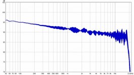
Next up, raw in-room of the unshaded array:

That looks pretty good, I have to say. That might explain why it can sound pretty good too 😉.
A new comparison between the two:

Clearly there is potential in the shading. There is improvement over the complete frequency response, the least amount of improvement between 1 and 4 K*. Top end and overall, I'd say shading wins a lot of points.
* = I already tried to win something there, it isn't that easy. It isn't bad either, but I was hoping to get it in line with the higher regions.
Is it enough to warrant the expense and troubles of an array operation? Pretty hard to answer, but i think so. Little things can go a long way...
That looks pretty good, I have to say. That might explain why it can sound pretty good too 😉.
A new comparison between the two:
Clearly there is potential in the shading. There is improvement over the complete frequency response, the least amount of improvement between 1 and 4 K*. Top end and overall, I'd say shading wins a lot of points.
* = I already tried to win something there, it isn't that easy. It isn't bad either, but I was hoping to get it in line with the higher regions.
Is it enough to warrant the expense and troubles of an array operation? Pretty hard to answer, but i think so. Little things can go a long way...
Attachments
I downloaded an active GIF tool a week ago but haven't played with it yet 🙂
It makes for a fun and easy to see comparison 🙂
(and fun avatars 😉)
Attachments
Last edited:
- Home
- Loudspeakers
- Full Range
- The making of: The Two Towers (a 25 driver Full Range line array)