As said, I wanted to see the influence of the room on the graphs, which is why I made the previous comparisons.
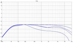
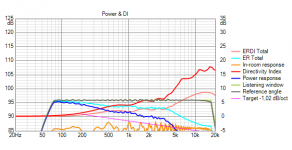
So lets look at the graph, without floor and ceiling again:

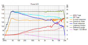
And compare it to the graph with floor and ceiling reflections (reduced level) on:

The unshaded graph seems to grow exponentially, once we add the reflections.
Which should not be a surprise, as we've removed a lot of drivers joining in on the higher notes in the shaded example. They are still playing, but at a lower level.
I'd say it makes a pretty strong case for the 'frequency dependent' shaded array. But what if it removes a feel of DDR, unintentially 😀.
So lets look at the graph, without floor and ceiling again:
And compare it to the graph with floor and ceiling reflections (reduced level) on:
The unshaded graph seems to grow exponentially, once we add the reflections.
Which should not be a surprise, as we've removed a lot of drivers joining in on the higher notes in the shaded example. They are still playing, but at a lower level.
I'd say it makes a pretty strong case for the 'frequency dependent' shaded array. But what if it removes a feel of DDR, unintentially 😀.
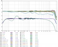
Still making slow progress, comparison between version 10.0 and 11.0. Target is better 'standing height' performance while not making the other heights worse.
See the scale on the left, 2 dB division. Meaning I'm down to plus/minus 1 dB over the entire range up till 10 KHz. Plus/minus 2 dB for everything above 10 KHz. (standing height confirms to that by itself between 100 Hz and 10KHz)
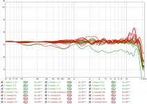
Same v.11.0 results compared to the Unshaded array...
The standing performance of version 11.0 has no greater deviation than the unshaded array. It's balance is darker, no doubt. But I'd rather have darker than brighter.
Raw in-room curves... Top end deviation max 6.6 dB for version 11. Top end deviation 21.9 dB for unshaded array.
Shaded is performing more uniform across the board. Plus/minus 2 dB up to 10 KHz vs plus/minus 4.9 dB for the unshaded array. Well over a 50 percent improvement. Much better than the 30 percent gain I started with. 🙂
Only detail improvements in the schematics. Trying to balance the frequency response over the entire range. This could be the winner. I've tried many things so far.
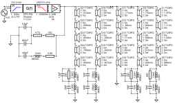
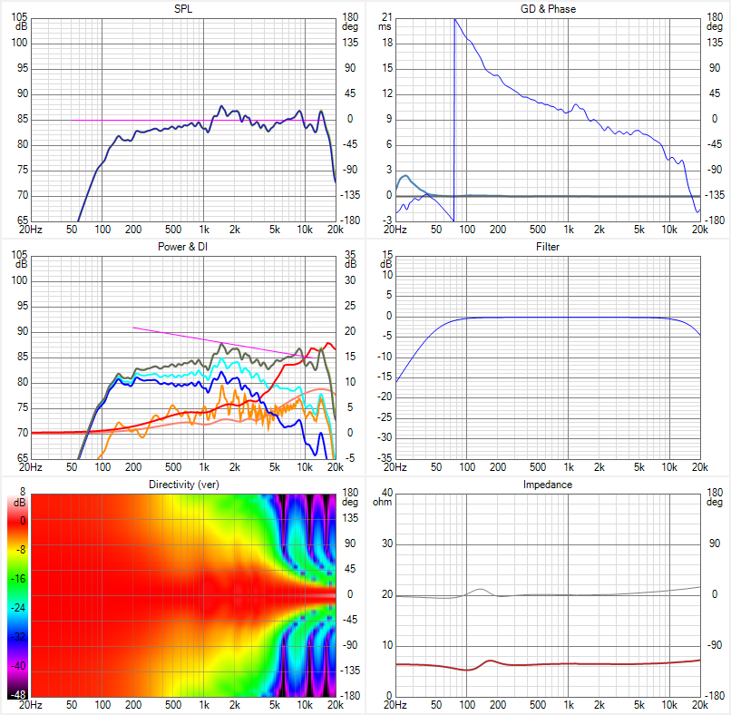
The schematic:
Completely done with passive components. That was my goal.
The shading in a pretty graph:
(prior to applying EQ)
5 drivers sharing the top end EQ load (not stressed more than in the unshaded array, even one dB less EQ). The next group is divided with two drivers above and three drivers below the central group. Gradually reducing output, but I have to maintain some of it to maintain decent performance standing up. Next up, 2 groups of 5 drivers, the top group has been adjusted to maintain the standing performance, bottom one is optimised for the listening window below 1 meter.
One more group, making it 5, that only helps out in the bottom end.
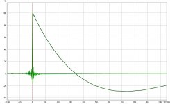
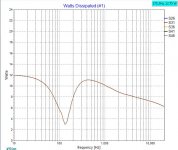
IR and STEP (shape of STEP determined by the cut-off frequency of 50 Hz)
Attachments
Last edited:
Cross post of me from the multiway forums here: https://www.diyaudio.com/forums/multi-way/266417-line-array-prototype-waveguide-cbt-shading-6.html#post6239293
Trying to show the differences between using a single driver vs an array, in room.
Let's do some simple sims. First up, a single TC9 in vituixcad (because I have the model in there already) and 1 watt power on that driver (2,83 volt output):
Now let's look at an array of 25 of those drivers, in this example they are representing a frequency shaded straight array (just because I'm playing with shading models in vituixcad at the moment). To get the same 1 watt on the driver, I need to output more power in the total array, which still has the nominal 8 ohm load, 5x parallel and 5 groups of those in series (14,14 volt output, to reach the same 1 watt load per driver):

So with the same 1 watt load (but this time on all drivers) I'm 10 dB higher on total output potential. Despite the subtractive interference. But I'm only looking at output potential. Not efficiency for one watt.
So I do see more potential for the array, even in the top end of an arrayed driver.
These sims do have a reduced floor and ceiling influence 'on' and both would need EQ to be flat in room, but look at the pro's of the array. Less influence from floor and ceiling and still a lot more output potential overall. Despite the lower efficiency of the array in the top end.
Basically, it can eat a lot more power before we get into trouble. It will be louder, no doubt about that! And judging the graph of the array should make clear that the midrange would only need a fraction of that single watt on each driver to match the output of a single driver.
Just some food for thought...
Trying to show the differences between using a single driver vs an array, in room.
Let's do some simple sims. First up, a single TC9 in vituixcad (because I have the model in there already) and 1 watt power on that driver (2,83 volt output):
Now let's look at an array of 25 of those drivers, in this example they are representing a frequency shaded straight array (just because I'm playing with shading models in vituixcad at the moment). To get the same 1 watt on the driver, I need to output more power in the total array, which still has the nominal 8 ohm load, 5x parallel and 5 groups of those in series (14,14 volt output, to reach the same 1 watt load per driver):
So with the same 1 watt load (but this time on all drivers) I'm 10 dB higher on total output potential. Despite the subtractive interference. But I'm only looking at output potential. Not efficiency for one watt.
So I do see more potential for the array, even in the top end of an arrayed driver.
These sims do have a reduced floor and ceiling influence 'on' and both would need EQ to be flat in room, but look at the pro's of the array. Less influence from floor and ceiling and still a lot more output potential overall. Despite the lower efficiency of the array in the top end.
Basically, it can eat a lot more power before we get into trouble. It will be louder, no doubt about that! And judging the graph of the array should make clear that the midrange would only need a fraction of that single watt on each driver to match the output of a single driver.
Just some food for thought...
Never thought of making this example until I stumbled over a post by Patrick, stating the output of an array would depend on the top end ability of a single driver. This isn't completely true. Though with smaller drivers you could get an even better result on the top end. Giving up the output potential on the other side. I still think the TC9 is a great middle of the road choice if you want full range arrays.
Maybe I should EQ the single driver flat and look at a few heights like we did for the array. That's for another time...
Maybe I should EQ the single driver flat and look at a few heights like we did for the array. That's for another time...
Let's compare the different heights of a single driver vs the array:

Clearly, a single driver could be considered well behaved vs the array. That is, if one takes the necessary EQ steps to get this in room result.
The dynamic difference is close to what you could expect, each one of the drivers in the array are getting by on less than a watt (each), despite the used EQ. Its SPL level is 10 dB higher than the single driver.
If we boost up both to see the max SPL figures they can safely reach at 2.7 meter:

Single driver at 15 watt... orange line is SPL level in room. In all honesty, the curve below 160 Hz is exceeding maximum power for this driver by a large margin. It had a 12 dB boost at 80 Hz to make it flat to that figure of 86 dB. Above about 160 Hz there is minimal EQ (boost) needed
Now the same graph for the array:

Every separate driver of the array is getting no more than 15 dB. So still within its limits. Quite the difference in SPL capacity.
(again, look at the orange line)
Now not all room anomalies are factored in here. Meaning in real life we won't be able to get this much, but it clearly shows why listening on the array at about 85 to 87 dB on average is a pleasure, and with the single driver it could become torture at those levels. The array has enough headroom for peaks while staying within the limits of the drivers used.
It can eat up to about 240 watt before exceeding these limits. Boost here is down to 50 Hz, I used up more headroom by boosting to lower frequencies. With the subs added, I can reach my goal of 105 dB in room (for peaks) without stressing the drivers. From a very low frequency (below 30 Hz) up to about 17500 Hz. That's where the dynamics observed come from I'd say. At the average the drivers are just loafing around. 20+ dB of headroom for peaks.
Clearly, a single driver could be considered well behaved vs the array. That is, if one takes the necessary EQ steps to get this in room result.
The dynamic difference is close to what you could expect, each one of the drivers in the array are getting by on less than a watt (each), despite the used EQ. Its SPL level is 10 dB higher than the single driver.
If we boost up both to see the max SPL figures they can safely reach at 2.7 meter:
Single driver at 15 watt... orange line is SPL level in room. In all honesty, the curve below 160 Hz is exceeding maximum power for this driver by a large margin. It had a 12 dB boost at 80 Hz to make it flat to that figure of 86 dB. Above about 160 Hz there is minimal EQ (boost) needed
Now the same graph for the array:
Every separate driver of the array is getting no more than 15 dB. So still within its limits. Quite the difference in SPL capacity.
(again, look at the orange line)
Now not all room anomalies are factored in here. Meaning in real life we won't be able to get this much, but it clearly shows why listening on the array at about 85 to 87 dB on average is a pleasure, and with the single driver it could become torture at those levels. The array has enough headroom for peaks while staying within the limits of the drivers used.
It can eat up to about 240 watt before exceeding these limits. Boost here is down to 50 Hz, I used up more headroom by boosting to lower frequencies. With the subs added, I can reach my goal of 105 dB in room (for peaks) without stressing the drivers. From a very low frequency (below 30 Hz) up to about 17500 Hz. That's where the dynamics observed come from I'd say. At the average the drivers are just loafing around. 20+ dB of headroom for peaks.
Attachments
Last edited:
Which one would be better for the resistors in the shading schematic, mox or ceramic?
If I put two in series, there's about a 6 watt load max on the biggest value I need. And that's running full out on max performance. As the TC9 is about 15 watt, two resistors of 10 watt in series should be able to handle anything, right?
The coils will probably be aircoil, 1mm to keep costs reasonable while keeping their resistance in check...
12.0mH 1.00mm Air Core Wire Coil Rdc 2,230 Ohm | RumoH - Caps, Coils and Speakers
Then there's the caps to worry about... As it really made a difference I'd like to include those to. MKP would probably be ok, but I can't find their dimensions. Ah... found it, 19mm diameter x 35mm length.
Last edited:
Running your sim model and using back of knapkin, I get 10W worst case for a 10 ohm resistor in series with 5 TC9's. Two in series overkill but you don't want to smell them cooking either. I think the main thing in R selection is not to choose wirewound.
I'm running 240 watt sims (max figure that would leave all 25 drivers within specs, even x-max) and it gave me a 12 watt load. To keep temperatures down I figured I'd be safe to use two in series 🙂.
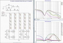
I've put the schematic into X-Sim to see the load on each component.
Looks like a 10 watt mox resistor would be enough for even the biggest value needed.

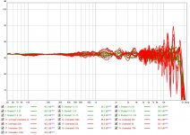
One driver presented from each string of drivers. Comparing it to an unshaded array:

So the load on the 5 center drivers playing full range does not change (as expected). The resistance of the air coil determines the output on the low end for the upper 5 drivers. (that are mostly just helping out on the bottom end)
I guess an iron core inductor could be used as they don't contribute much to the midrange. Just to get the resistance lowered while keeping the price of the inductor reasonable.
Looks like a 10 watt mox resistor would be enough for even the biggest value needed.
One driver presented from each string of drivers. Comparing it to an unshaded array:
So the load on the 5 center drivers playing full range does not change (as expected). The resistance of the air coil determines the output on the low end for the upper 5 drivers. (that are mostly just helping out on the bottom end)
I guess an iron core inductor could be used as they don't contribute much to the midrange. Just to get the resistance lowered while keeping the price of the inductor reasonable.
Attachments
I've spend some time and energy trying to improve upon these last results. As I'm not ready to give up on the balance while standing up, this wasn't exactly easy.
If I do find some improvement, I will post the schematics. I've already tried numerous things i could come up with, but did not find much room for further improvements. That is, as long as I'm trying to preserve a reasonable output curve at standing heights.
The passive components will be around 200 euro in total as specced from the last schematic i presented. That's with MKP capacitors, air coil inductors with 1mm wire and 10 watt Mox resistors from Jantzen, the superes, and using 2 in series to spread the load (to keep temperatures down).
Almost ready to commit, but I did have to try and optimise the results at least one more time before committing fully.
No idea when I'll be able to operate on the arrays, so don't expect anything soon. I also still need to find the time to build my desired 6 channel pré-amp. The buffers and power supply are in my posession, I need to source all in and outputs and determine if I also want differential/balanced inputs right from the start. Right now RCA would work fine, but I do want to have the outputs both with RCA and balanced.
Ideally I'd do one thing first and then move on to the next step, but maybe I'll have to live with a few upgrades all done at the same time.
For the foreseeable future I won't have as much time alone to play as I once had. So things move more slowly.
Last edited:
I did consider that, but as I have a low shelf that's reducing output on all drivers on the low end I did not go as far. The remaining 5 drivers do not get more power than in the full range array, so basically their role will not change compared to previous duty.
(as is, with subs added, their motion will be way less than you'd expect)
(as is, with subs added, their motion will be way less than you'd expect)
Hello sir,
First of all, compliments for the enormous and well-documented thread you have on hands. I have just started reading and I think I will have a lot of try-outs and experiments in the reading I still have ahead of me. A lot of info is on point.
I wish I was knowledgeable enough to help you out here, but I'm limited in experience with one tweeter only. I do plan on having an experimental array of vintage ribbon tweeters, but I am struggling to source enough of them to make an array that covers the range that my ears travel when sitting and standing. I will be delighted to hear about your solutions regarding this and wish you the best of luck with your project.
Sincerely,
I don't think there was ever a clearer trade-off in audio than choosing between smoothing top end response by shading an array and keeping a wide enough vertical window for both seated and standing listening. The ripple we are trying to smooth comes from subtractive combining which can be reduced or even eliminated depending on how much contributions from more distant drivers are attenuated and when vs frequency. But the usable vertical window can never be taller than the height of the unshaded+lightly shaded portion of the array. If that portion gets too tall than the drivers near its edges combining subtractively at the highest frequencies. Once the ear is above or below that lightly shaded portion of the array, driver directivity begins to reduce the treble. So there is a physical limit we are up against. What you've got might be as good as it gets unless you give up some smoothness in the seated position to improve the standing position.I've spend some time and energy trying to improve upon these last results. As I'm not ready to give up on the balance while standing up, this wasn't exactly easy.
And I think you've done rather well. I've pretended not to care about standing listening while optimizing the seated height response. That makes my standing height response worse than yours, with a large bass hump which may or may not be leveled out by response from the rest of the room. That isn't so much a boost in the low end as a progressive loss of energy towards the high as I'm doing frequency shading rather than amplitude shading.
I went back and looked at my unshaded array simulations. It simulates within +/- 3db over the seated through standing heights when equalized to an average overall all those heights (undulating with frequency while staying flat on average) but I thought and still think it sounds great. It would be silly to improve the measured seated response beyond the point at which I can hear the improvement because the improvement isn't free.
I don't know how we can make this tradeoff between seated and standing other than by listening tests.
I don't think there was ever a clearer trade-off in audio than choosing between smoothing top end response by shading an array and keeping a wide enough vertical window for both seated and standing listening. The ripple we are trying to smooth comes from subtractive combining which can be reduced or even eliminated depending on how much contributions from more distant drivers are attenuated and when vs frequency. But the usable vertical window can never be taller than the height of the unshaded+lightly shaded portion of the array. If that portion gets too tall than the drivers near its edges combining subtractively at the highest frequencies. Once the ear is above or below that lightly shaded portion of the array, driver directivity begins to reduce the treble. So there is a physical limit we are up against. What you've got might be as good as it gets unless you give up some smoothness in the seated position to improve the standing position.
And I think you've done rather well. I've pretended not to care about standing listening while optimizing the seated height response. That makes my standing height response worse than yours, with a large bass hump which may or may not be leveled out by response from the rest of the room. That isn't so much a boost in the low end as a progressive loss of energy towards the high as I'm doing frequency shading rather than amplitude shading.
I went back and looked at my unshaded array simulations. It simulates within +/- 3db over the seated through standing heights when equalized to an average overall all those heights (undulating with frequency while staying flat on average) but I thought and still think it sounds great. It would be silly to improve the measured seated response beyond the point at which I can hear the improvement because the improvement isn't free.
I don't know how we can make this tradeoff between seated and standing other than by listening tests.
Hi Jack, that all makes complete sense to me, and mirrors the experimentation i did with frequency shading with me 24 TC9 straight array.
Question though... would your take change on...
"But the usable vertical window can never be taller than the height of the unshaded+lightly shaded portion of the array. "
.... if for the entire height of the array, the c-to-c spacing at 20kHz was essentially continuous and without any shading, like in a tall ribbon or planar ?
Seems to me this would provided equal HF/VHF to all heights...????
Well standing height does not need to be perfect for me. It needs to be balanced well enough to still sound good. I've already done tests to mimic what I get after this shading is applied. I can live with that.
The main reason for me to go forward with this is that improved top end. I've put it through many more simulations than the ones shown here, the balance throughout the entire spectrum seems to benefit for almost all listening scenarios I can come up with.
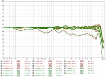
I've made minute changes to my last attempt. It's hard to see any difference, but I'm aiming to go back to single point correction, while keeping a balanced sound over a wide area. The more tight bundling of the top end should help to achieve that goal.

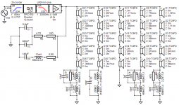
The schematic:

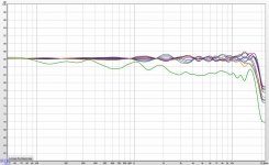
As seen with this 2 dB scale, it doesn't look bad. I hope I word it right to show the bundling I was after. It rotates across the (average) center line and mimics what an unshaded array looks like. It's even better behaved over a wide area and has way less true peaks and dips than the unshaded array.
The plots are covering plus/minus 10 cm around the 1 meter listening height with 2.5 cm steps. The 'standing' plot is at 1,7 meter.
You'll be hard pressed to see any true differences compared to the last plots I posted. Minute changes that I feel will help the overall result and goal to get effective correction made at a single spot (or maybe at ear positions).
Almost ready to order components. Someone needs to try this, right? 😀
Disclaimer: I do not do this because I'm not satisfied with what I've got so far. It's merely curiosity driven. I need to remove my speakers from the room anyway, so I might as well give it a try. It looks like the work on our living room starts next week, so time to move the speakers out of the way.
It will be a while before I get back that living room space and will learn what it does exactly. So don't hold your breath. 😉
The main reason for me to go forward with this is that improved top end. I've put it through many more simulations than the ones shown here, the balance throughout the entire spectrum seems to benefit for almost all listening scenarios I can come up with.
I've made minute changes to my last attempt. It's hard to see any difference, but I'm aiming to go back to single point correction, while keeping a balanced sound over a wide area. The more tight bundling of the top end should help to achieve that goal.
The schematic:
As seen with this 2 dB scale, it doesn't look bad. I hope I word it right to show the bundling I was after. It rotates across the (average) center line and mimics what an unshaded array looks like. It's even better behaved over a wide area and has way less true peaks and dips than the unshaded array.
The plots are covering plus/minus 10 cm around the 1 meter listening height with 2.5 cm steps. The 'standing' plot is at 1,7 meter.
You'll be hard pressed to see any true differences compared to the last plots I posted. Minute changes that I feel will help the overall result and goal to get effective correction made at a single spot (or maybe at ear positions).
Almost ready to order components. Someone needs to try this, right? 😀
Disclaimer: I do not do this because I'm not satisfied with what I've got so far. It's merely curiosity driven. I need to remove my speakers from the room anyway, so I might as well give it a try. It looks like the work on our living room starts next week, so time to move the speakers out of the way.
It will be a while before I get back that living room space and will learn what it does exactly. So don't hold your breath. 😉
Attachments
Last edited:
Hi Jack, that all makes complete sense to me, and mirrors the experimentation i did with frequency shading with me 24 TC9 straight array.
Question though... would your take change on...
"But the usable vertical window can never be taller than the height of the unshaded+lightly shaded portion of the array. "
.... if for the entire height of the array, the c-to-c spacing at 20kHz was essentially continuous and without any shading, like in a tall ribbon or planar ?
Seems to me this would provided equal HF/VHF to all heights...????
Hard to tell. But it isn't as simple as that I'm afraid. I know Owen (member: opc, one of the first with TC9 arrays on the forum) has tried with the long BG planar, the rd75. You can read about it here: https://www.diyaudio.com/forums/multi-way/284371-corner-floor-ceiling-line-array-using-vifa-tc9-21.html#post4699086
Not quite the floor to ceiling length, if you can match the planar on the bottom end it might be a superb combination, maybe like StigErick has shown with his multiple 21" woofers (8 of them). 😀
Build quality of the B&G rd75 ribbons has not been great though, and it seems they are not available anymore.
Hi Jack, that all makes complete sense to me, and mirrors the experimentation i did with frequency shading with me 24 TC9 straight array.
Question though... would your take change on...
"But the usable vertical window can never be taller than the height of the unshaded+lightly shaded portion of the array. "
.... if for the entire height of the array, the c-to-c spacing at 20kHz was essentially continuous and without any shading, like in a tall ribbon or planar ?
Seems to me this would provided equal HF/VHF to all heights...????
It should. You are describing a continous line source. Put that in a room with reflective floor and ceiling and you have the mythical infinite line array.
All the ripple in the FR of a discrete line array can be traced to the spacing between drivers. But the equalization to smooth out that ripple is position dependent so once you smooth it out, you no longer can have the same response at all heights. Its the same catch22 as getting rid of the ripple by shading.
Hard to tell. But it isn't as simple as that I'm afraid. I know Owen (member: opc, one of the first with TC9 arrays on the forum) has tried with the long BG planar, the rd75. You can read about it here: https://www.diyaudio.com/forums/multi-way/284371-corner-floor-ceiling-line-array-using-vifa-tc9-21.html#post4699086
Not quite the floor to ceiling length, if you can match the planar on the bottom end it might be a superb combination, maybe like StigErick has shown with his multiple 21" woofers (8 of them). 😀
Build quality of the B&G rd75 ribbons has not been great though, and it seems they are not available anymore.
I used to have Carver Amazing Platinum Editions, which used a predecessor (IIRC) to the RD75 flanked by 4 12" woofers, open baffle. I loved them but never had measurement capability (or interest for that matter) while I owned them. Now you can get ( for big bucks) SoulSonics, a very high end version of the same concept. More practically, consider Newform Research ribbons - but you will run into other compromises chasing 2 way ribbon arrays.
Better to shade the full range arrays that we have. If the shading improves the high end sound as much as it does the measurements, we will really have something.
Maybe an enlarged version of the foam pads one of those RAAL tweeters has would suffice?
I've tried it with pillow stuffing on a pair of large MTM's and they sounded more open and detailed, where before they sounded quite suffocated in the higher mids and highs.
Measurement data looked almost exactly like it would have been one larger driver, but with better vertical dispersion IIRC.
I've tried it with pillow stuffing on a pair of large MTM's and they sounded more open and detailed, where before they sounded quite suffocated in the higher mids and highs.
Measurement data looked almost exactly like it would have been one larger driver, but with better vertical dispersion IIRC.
- Home
- Loudspeakers
- Full Range
- The making of: The Two Towers (a 25 driver Full Range line array)