I was just playing with asymmetrical types and orders, along with separate xover frequencies. Measurements again, I'm done with the dirac filtered imports Lol.
Looks like you're right about real world rearing up, if that's what folks want to do with their xovers.
First, obvious problem is what filter freq do you chose when HP and LP are different freqs?
But what really gets me is look at the following:
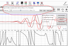
A BW4 at 116Hz LP summed with a 90Hz LR16 HP....thought I'd whack it up a bit. A 1/3 oct impulse filter at 100Hz is used.
The thing is: the 1/3 oct impulse overlay alignment is correct !!!
Any shift would make would be incorrect.
See how REW SPL and phase agree with Responsalyzer....
I guess 1/3 oct wants complementary xovers.... if traces are to be aligned...which is ALLRIGHT by me 😀

Looks like you're right about real world rearing up, if that's what folks want to do with their xovers.
First, obvious problem is what filter freq do you chose when HP and LP are different freqs?
But what really gets me is look at the following:
A BW4 at 116Hz LP summed with a 90Hz LR16 HP....thought I'd whack it up a bit. A 1/3 oct impulse filter at 100Hz is used.
The thing is: the 1/3 oct impulse overlay alignment is correct !!!
Any shift would make would be incorrect.
See how REW SPL and phase agree with Responsalyzer....
I guess 1/3 oct wants complementary xovers.... if traces are to be aligned...which is ALLRIGHT by me 😀
I still have beta 22 installed, that might explain the differences. However it would be a shame to lose the option of fine tuning impulse responses. I've used it often to try some theories (like these Filtered responses).
Doesn't pressing that offset button lead to a setting box of its own? Where we can shift an IR by entering numbers?
I would expect it to do that, as can be read in the old manual: Impulse Graph
Can't think of a single reason to edit out that useful option. 😱
The offset button offers a setting box, but it is a sliding action (not +/- arrows) and it is impossible to "dial in" small values. It is too coarse and has no fine control over the value, unfortunatelly.
EDIT: just realized it can be controlled with left/right arrow keys in fine steps. Was using mouse only before....so it seems to work, only looks differently.
Attachments
Last edited:
Thanks for confirming! Glad it does work. I think one should be able to type in the figure you'd want. Either a delay or an advance.
Without a proper time locked measurement it is unlikely to work right every time. There can be many propagation delays in an audio system every time something is processed. These are not always stable either. When you tried a plain TC9 by itself without processing it all worked so I would be looking at your hardware processor to eliminate that as a variable.
Are you using a USB Mic or an analogue mic into an interface?
If it is USB an acoustic timing reference should help, if it is analogue then a loopback timing reference is even better. The loopback timing is like what ARTA does in dual channel mode comparing the input to the reference signal.
Kimmo has a good write up on how to take measurements to work with VituixCAD. This is the first thing that is mentioned because without time locked measurements nothing else will work.
All my recent measurements re peak vs start or 1/3 oct filter, have been solely electrical from a processor, so no mic involved.
They were using a Behringer UMC404 sound card to interface the processor.
I routinely use loopback for all acoustic measurements, with several analog mics and the UMC404.
I also normally use loopback for purely electrical measurements, but have been playing with it off to try REW's other settings, hoping to discern any difference in REW's handling of measurements vs imported impulses.
Since I couldn't find any mistakes with the procedures I've been using {I always suspect user error first 😉},
I went to work on clocking errors as you suggested.
I found q-sys also allows a processor design be nothing more than soundcard-out to soundcard-in, inserting whatever components you want in between.
So no external loopback cables or ADC conversions. Pretty neat really. It even has counters that keep track of any USB sample slippages vs the master processor clock.
Bottom line, I'm getting measurements now that look just like imported impulses from rephase 😀
It's amazing me what a few samples moved this way or that way can do to the measurements.
I gotta go post to BYRTT now, and let him know I'm back in the fold, having got measurements to finally match theory 🙂
Thx for your continued ongoing help !
Hi BYRTT, pls see the reply i just posted to Fluid.
Thx for hanging in with me as I struggled to get to the bottom of the discrepancies i was seeing...
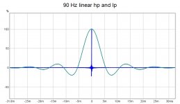
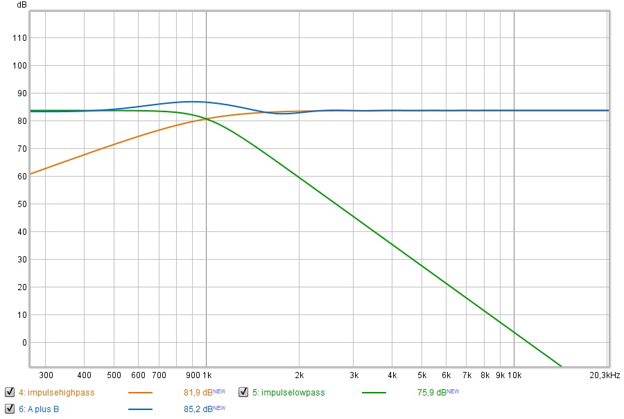
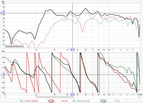
Here is a measurement that finally matches what I could get with theory & rephase imports.
90Hz 100dB/oct linear phase HP and LP...
impulses center aligned as you knew they would be...

Thx for hanging in with me as I struggled to get to the bottom of the discrepancies i was seeing...
Here is a measurement that finally matches what I could get with theory & rephase imports.
90Hz 100dB/oct linear phase HP and LP...
impulses center aligned as you knew they would be...
Attachments
For instance it should be usable on a Harsch type crossover too:
Not a standard type of crossover, put pretty hard to get right conventionally.
It sums +3 dB around the crossover point but has excellent group delay without being a linear phase variant. It's all minimum phase.
More here: S. Harsch XO
Hi Wesayso, as you'll see in my posts to Fluid and BYRTT, it ended up being a timing/clocking issue separating my measured results from import results.
Big thanks to all three of you for you ongoing help...it's hard to find the degree of expertise with these things like you guys have accumulated.
The Harsch xover does look like like it's a very good candidate for 1/3 oct alignment.
I've been playing with a handful of assymetric xovers with the new soundcard routing in place, and 1/3 patterns make much more sense in their variations.
My take so far is it's pretty clear asymmetric types, orders, and frequency keep alignments from laying neatly on one another, but patterns that hold in most circumstances may be there to use...
Hi BYRTT, pls see the reply i just posted to Fluid.
...
.....
 and thanks to fluid : ) actually i yesterday prepared some arguments and visuals where some of it was in spirit of fluids good post but was hindered by other life stuff find time to post, upon the good tips mark remember use same rate for synthetic created targets as real world mesumerement chain run in and also if live sweep is say FDW filtered remember also FDW filter the synthetic targets because rate and FDW filtering makes a difference, well at least it does in my studys.
Now i cant stop post few of the prepared visuals from yesterday in think they funny because i made them animated in amateur Element version of photoshop.
Below example was to argue correct curve of target slope the first -30dB down is important and LR kind of rocks, animation toggle each 500mS to BW slope that have phase coherence but amplitude sum is not really flat... : )...:
This animation is expansion on wesayso's filtered IR in one can make multiple response copy of real world sweep and do same for synthetic target one, in below IIRC we are FDW filtered 1/6 and it toggle my indoor sweep verse synthetic for setting a known target few years ago:
Attachments
Last edited:
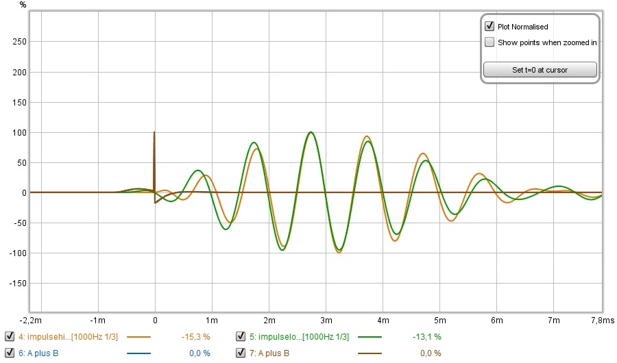
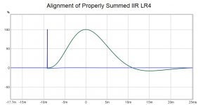
Aligning the peaks of IIR filters (without 1/3 oct filtering) will result in a dip as shown below.

Correct alignment (which is easy for an LR crossover using wesayso's waveshape method) looks like this

The issue in saying it is the start of the IR in practice is determining where that is. Without a time locked measurement trying to work it out from the impulses would be very hit and miss. Hard to see where the start is in the graph above.
Correct alignment (which is easy for an LR crossover using wesayso's waveshape method) looks like this
The issue in saying it is the start of the IR in practice is determining where that is. Without a time locked measurement trying to work it out from the impulses would be very hit and miss. Hard to see where the start is in the graph above.
Attachments

I still think that being able to add a user configurable number for an 1/3 octave filter (thus at a frequency of our own choice) should help within REW to use it as a crossover tool.
Not something I need specifically, but a nice to have feature.
Maybe I'll suggest it, John also incorporated the APL_TDA-'like' wavelets after bugging him about it for a while 😀.
Not something I need specifically, but a nice to have feature.
Maybe I'll suggest it, John also incorporated the APL_TDA-'like' wavelets after bugging him about it for a while 😀.
I've put in a request: Feature request, self defined 1/3 octave filters | AV NIRVANA
I'm not relying on the outcome, but I do think it could be of use to many people. Especially those that have limited means within DSP and can't make perfect complementary crossovers. Looking at the filtered frequency where the acoustic sum is supposed to be should be of help in those cases.
I'm not relying on the outcome, but I do think it could be of use to many people. Especially those that have limited means within DSP and can't make perfect complementary crossovers. Looking at the filtered frequency where the acoustic sum is supposed to be should be of help in those cases.
Nice Wesayso,
The more i think about it, the more i think the 1/3 technique might be a big help with REW.
Because i think actual acoustic speaker measurements are much more likely to be complementary, than asymmetrical.
Just for clarity, i think of complementary as summing to flat magnitude thru the xover summation region, and having the same coincident phase traces whatever the slope. So complementary applies to both IIR and linear phase.
Please let me explain...and also dwell on some general xover theory if I may.
It seems to me, if an electrical xover is properly done, then acoustically, drivers have to sum to flat magnitude and to the same phase slope thru the xover region.
So by definition, the acoustic xover ends up being complementary.
This line of reasoning kinda begs the question, shouldn't all speakers end up with acoustically complementary xovers ?
Intuitively, it seems yes....
But no doubt there are special cases (beam steering or assymetric pattern control) ...can't think of any others though, and such would probably fall well outside the realm of DIY speaker tuning ...
I'd like to contrast two methods of creating xovers, because i think it further illustrates the above thoughts about how well-tuned speakers ending up acoustic complementary.
And if that's true, it strengthens the case for the 1/3 technique working well imo.
As some know, I often advocate making a xover by first flattening the in-band and out-of-band response of drivers thru their summation regions, and then applying complementary xovers.
In-band need no discussion, it's out-of-band that is interesting.
The flattening of the drivers out-of-band should be thought of as an intermediate step that MUST have a xover applied to it.
The summation of the out-of-band flattening with the complementary xover ends up being the total electrical xover.
And strongest odds are that will not look exactly like any named xover.
And one driver's electrical xover will not be symmetric with with the summing driver's counterpart.
The two total electrical xovers will not sum complementary, electrically.
But the acoustic driver summation will sum complementary 🙂
I think many people can see, if drivers had flat response, then adding complementary electrical xovers will give complementary acoustic response.
That method just makes them synthetically flat as an interim step, toward build a total xover.
The much more common method, is to say hey, drivers don't have flat response,
so i will experiment with different xovers on both drivers, by type, order, polarity, delays, etc...until a nice smooth mag and phase summation is measured acoustically.
And end up with non-symmetric xovers that will not sum complementary, electrically. (just like the prior method)
But the acoustic driver summation will sum complementary (just like the prior method) 🙂
Now here's what's really cool imo.....if we set our acoustic xover goal at some particular order, say for example 4nd order between drivers...
.....the two methods just discussed will end up making the exact same total electrical xover.
They have to...to satisfy an identity equation that says: electrical xover (including EQs) + driver response = acoustic response.
All the trial and error adjustments in the common method must equal the pre-flattening summed with complementary xover method....if the speaker has the desired acoustic summation in place.
What this means to me, is that the 1/3 technique is more likely to work well, because it is being used against measurements (acoustic) that are closer to complementary than not.
It hit me as I was measuring a bunch of assymetric xover types electrically, checking out the 1/3, and getting decent but varying harder to make sense of results,
that hey...who cares about electrical xover summations anyway, for actual speaker tuning?
I've never once in my life looked to see how two adjacent FIR filters built off raw driver measurements, summed electrically.
My entire reasoning rests on the idea that acoustic xovers need to be fully complementary, if speakers are tuned properly.
If this idea has holes in it, pls hit it up.
If it's true, i think the 1/3 technique gets alot more valuable.
thx for listening...
I can think of a few reasons why you could opt for an asymmetrical crossover. 🙂
I've used them in my Car for instance, between my XT25 tweeter and Herz 6.5" woofers. All I had available to do a good job were named crossover types and an overall 1/3 octave EQ (edit: and time alignment on each driver). So no extra options to get woofer break up out of the way with notches etc. I ended up with a partial filter over the tweeter and an asymmetrical crossover filter to have the woofer roll off fast enough to avoid its nasty response from messing up the end result.
All in all it ended up sounding quite good, it was the reason for me to up my game in my home.
At that time I made the crossover by playing a sine wave with the exact frequency of the crossover and reverse one driver's polarity. With an SPL meter at the listening spot I looked for the least output at that frequency (it had time alignment, based on distance to each driver).
After that basic alignment (which sounds easier than it was), I used the graphic equaliser to get the FR curve back in shape.
I even had a subwoofer in there which was tuned in a similar way. It was quite simple to mess up and align the drivers being one sample off.
The advantage of setting up audio in a car: your head is more or less always in the same position/spot.
The disadvantages: to many to mention 😀. Yet with proper care and dedication it was a very rewarding learning process and I did get very satisfying results.
Even more important, it started the learning process while reading lessons from people like Lycan/Werewolf.
The above is an example of why things aren't always as easy as we'd like it to be. Sometimes you just got to make due with what you've got.
Adding this new feature in REW can help get it in shape real quick even when it's limited to being used as a visual confirmation.
We've got to be aware not all people are nutcases like us, trying to get to the bottom of things. Sometimes they simply lack the means to do more.
Many reasons can be found why there's always more than one road to travel.
Heck, when someone asks for crossover help, usually I'm glad if I succeed to point out that it is the acoustical shape that matters.
That you just can't just pick a crossover slope from a drop down list and everything will be perfect. 🙂 Try and convince them, they are
pretty sure of themselves they actually have that Linkwitz Riley crossover in place!
Edit: all that being said, it might be useful if people that like the idea of adding the user defined 1/3 octave filter to REW said so on that topic I started.
The more support it gets, the more it will continue to ring in the mind of John to see if he could integrate it. At least, that's what happened with the APL_TDA wavelets.
Last edited:
Well, for a XO to work well we can't only look at the meeting point... also the stop bands need to behave. Some recommend that the two octave of "stop-band-2-B" shall be FR wise linear both in level and phase in order for your XO to work properly. In all directions... (or your total power dissipated will not be 100% at all freq in the room) Easy piecy 🙂
//
//
Last edited:
Get it to behave till it's about 30 dB down and you'll do well enough to get satisfying results under most circumstances. Do better than that if you have the means to do so.
30 dB down is reached earlier with steep crossovers, however each crossover has it's own set of compromises.
Mark's method of first getting flat frequency curves well past the crossover point (on both sides) is a good way to ensure things will work out.
In real live, placement might screw with things as reflections will likely obscure the measurements. What to do then?
In fact, I see a lot of people measuring up close and designing their crossover that way. Ignoring the fact that the distance to each driver may change once we're at an actual listening distance. If you have the crossover within a quarter wave distance center to center spacing between drivers, you'd still be OK. But more often than not such a distance has not even been used. In cases like that I'd prefer to adjust any timing at the listening position. And good placement in order to deal with any reflections.
Sure the frequency curve did not become less important when using this method. However setting the crossover at a distance where you're actually listening still makes sense to me. As well as determining the effects of any room effects before one decides to go for a certain concept or placement.
So it isn't a substitute for thinking, one still has some work to do to get it right.
As said, I don't use a regular crossover with my arrays/subs. Still I'm perfectly capable to align them and have them sum better than each driver by itself. As that is how I can catch some room effects caused by placement. Kind of like using multi subs. The arrays don't even need to do much, but they still add and aid in getting a better overall sum.
All of this is done in linear phase. That is, phase following the bandpass behaviour of the total sum. Does that make it any more clear? I don't think so 😀. But I prefer this to simply using a complementary theoretical crossover as it simply works better this way inside my room with my specific placement limitations....
So there, another reason for non complementary crossovers, as the arrays do not have a crossover set, they have a low shelf with PEQ tweaks that determines their roll off.
Heck, when someone asks for crossover help, usually I'm glad if I succeed to point out that it is the acoustical shape that matters.
That you just can't just pick a crossover slope from a drop down list and everything will be perfect. 🙂
I hear you 🙂
Imho, until people realize that it is acoustic xovers that matter and not electrical, a tool like 1/3 octave impulse alignment is over their head and likely of little value to them.🙁
I also think even if people understand that acoustic xovers are what matter, until they realize that good speaker xover results will measure as acoustically complementary,
they can endlessly search for tunings with timings, various electrical xover settings, and not see or achieve the big-picture acoustic goal.
That was a part of my previous post, to help folks see what a properly built electrical xover will look like, in comparison to the fully complementary acoustic xover we desire measured from the speaker.
Like you say, you can't just pull a xover down from a list (unless you flatten out-of-band first 😉)
I think gathering support for a tool like 1/3 oct is also a task at showing how and when the tool will work to make good timings and alignments.
It's not a tool for electrical timings imo, because the inevitable electrical asymmetries needed will skew it up.
But I think it could be a good tool for both timing and acoustic alignment, because if 1/3 speaker overlays from high and low don't line up cleanly when timed together,
we know we haven't yet achieved a complementary acoustical xover that only needs timing to finish it up.
edit: just read your good followup post to TNT
+1 to all said
Last edited:
John showed me his Alignment Tool as a way of getting things right. The example plot on that page makes a good case for the 1/3 octave filter, as it isn't as neat or clear in phase alignment as one of your crossovers 🙂.
I think with even more ways like 3 or 4 drivers it would confuse a lot of people even more to get good results. In no way does this alleviate the need for good acoustic slopes. However it would offer the opportunity to break up each step into a more simple process. I'd prefer using the 1/3 octave filtered IR's to this phase alignment tool he showed.
In his picture:
If I were asked to help out there, I'd use a 50 Hz 1/3 octave filtered IR to align the drivers and I'd bet that it would align perfectly at the desired crossover frequency.
Last edited:
Yeah, lot's of ways to do this.
I've also been using the alignment tool as John showed for helping to square traces together..
That sort of phase alignment is what's taught in classes for Smaart and Systune, for live sound and professional install work.
It's what I'm familiar with, (and a big part of the reason I'm always advocating that mag and phase are all we really need....it never fails and gets intuitive after a while)
But that type phase alignment is much easier when there is continuous real time phase and mag to work with, as in Smaart's and Systune's (and i assume ARTA's) dual channel FFTs.
Mainly because it's easier to trust real time phase and mag traces that respond instantly as expected, to timing or xover changes.
I think with REW's static look, I might end up preferring the 1/3 oct technique once i feel i understand all its implications and nuances.
One thing i do know is that the 1/3 oct impulse look has been a hell of a good learning tool for me....thx again for showing me this several years back 🙂
- Home
- Loudspeakers
- Full Range
- The making of: The Two Towers (a 25 driver Full Range line array)