Copper does nothing good against magnetic fields. It is very good against electrical fields, though.
Only iron and especially Mu metal can stop magnetic fields to an appreciable degree. I would not be so concerned about magnetic fields in a high level buffer/amp construction. It is quite another matter with low level amps such as RIAA amps or still worse MC step up amps.
Only iron and especially Mu metal can stop magnetic fields to an appreciable degree. I would not be so concerned about magnetic fields in a high level buffer/amp construction. It is quite another matter with low level amps such as RIAA amps or still worse MC step up amps.
Here’s a website for the MU Metal sheets and rolls
http://custommagneticshielding.magneticshield.com/category/mumetal-sheet-and-foil
http://custommagneticshielding.magneticshield.com/category/mumetal-sheet-and-foil
Thanks guys, that MuMetal link is a cool one, I often see caged toroids, they do offer something like that.
So copper would be a good candidate to shield the pré-amp part?
I'd hate to need extra boxes behind the amps.
Anyway, lots of time to think about it, first I'll do the simple steps. At the other side where it is out of sight.
So copper would be a good candidate to shield the pré-amp part?
I'd hate to need extra boxes behind the amps.
Anyway, lots of time to think about it, first I'll do the simple steps. At the other side where it is out of sight.
If you are serious about multi channel analogue volume control have a look at something like this from a local in the netherlandsOne could build a killer pré-amp with these boards... Which is something that's also on my mind. As that could give me an option for introducing an analog 6 channel volume control to avoid using digital attenuation If I would choose that path.
CS3318VolumeControl 8channel
CS3318 is a very good chip.
Aluminium is almost as good, but the "cool" factor is less 😀Thanks guys, that MuMetal link is a cool one, I often see caged toroids, they do offer something like that.
So copper would be a good candidate to shield the pré-amp part?
I'd hate to need extra boxes behind the amps.
Anyway, lots of time to think about it, first I'll do the simple steps. At the other side where it is out of sight.
Still at these levels, I would say that there will be absolutely no problems even without an enclosure!!
No need to go overboard in shielding an OpAmp buffer at these levels. IMHO
If you are serious about multi channel analogue volume control have a look at something like this from a local in the netherlands
CS3318VolumeControl 8channel
CS3318 is a very good chip.
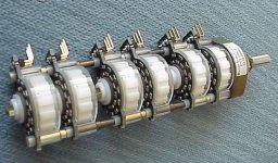
Interesting and affordable suggestion... here I was only looking at volume controls like this:
Simple, basic but expensive...
Attachments
Blatant knowledge theft 🙂
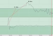
To time-align sub with main (main fixed, sub delay changeable)
Align as A or B - never got that really... on the peak or on the start?
To time-align sub with main (main fixed, sub delay changeable)
Align as A or B - never got that really... on the peak or on the start?
Attachments
Last edited:
Do you have a link to that review?
Review is from innerfidelity online magazine, here
Katz's Corner Episode 8: My Current Affair | InnerFidelity and here:
Katz’s Corner, Episode 7: Mosfet Magic | InnerFidelity
Unfortunately, I make mistake. Mr.Katz make comparison between TKD step. attenuator(not DACT), versus Muses.
So sorry for my neglect.
Anyway, hope, his review will be interesting for auditory.
Blatant knowledge theft 🙂
To time-align sub with main (main fixed, sub delay changeable)
Align as A or B - never got that really... on the peak or on the start?
Hard to determine, right? I remember that a certain representative from JBL used to have the answer to that over on the mobile audio forums. You had to pick a certain point on the upgoing slope of the sub peak.
However I've found at least two routes that worked better or more easy for me.
What I did in my own case is have one channel (either mains or sub) delayed vs the other. Next have them play the same frequency sweep and measure them together (both playing at once), say a sweep from 20 to 2000 Hz, as i know my sub can play that high.
That made it easy to see a sharper impulse peak from the sub. So I'd get 2 peaks, one smaller one (sub) and one clear peak and measured the distance in time between both peaks. This alignment worked for me because I do use a linear phase crossover, so I can align both waves (after first straightening the FR on them both) at the higher frequency and know that the'll align at the crossover frequency as well, because a linear crossover does not introduce delay.
I'm guessing you have a crossover in place here based on the shape of the peak of the sub. There is another option available.
That picture of yours doesn't look like an REW measurement but maybe your package also has a way to filter these measurements. That is my second option.
If you filter the measured impulse close to the frequency you want to use as crossover point you'll see a wave shape. Both should look somewhat similar after filtering. Making it easier to relate both signals to each other instead of having one high frequency peak and one showing a low frequency lobe.
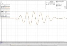
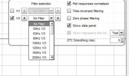
It should look somewhat like this when filtered:
This is a 1/3rd filter applied (to a Dirac pulse) at 160 Hz. Doing that kind of filtering for both measurements should make you able to see similar shapes and align them precisely. This should work for a normal crossover as well as a linear phase crossover. Real life measurements will look a bit more rough but the build up from the filtered frequency should still be clear enough to align the peaks and make sure they match. Count the wave shapes because you don't want to be off by a cycle 😉.
Attachments
Review is from innerfidelity online magazine, here
Katz's Corner Episode 8: My Current Affair | InnerFidelity and here:
Katz’s Corner, Episode 7: Mosfet Magic | InnerFidelity
Unfortunately, I make mistake. Mr.Katz make comparison between TKD step. attenuator(not DACT), versus Muses.
So sorry for my neglect.
Anyway, hope, his review will be interesting for auditory.
It certainly is interesting, thanks for the links.
For these stepped attenuators I see the namer DACT, Goldpoint and TDK often mentioned together.
Interesting and affordable suggestion... here I was only looking at volume controls like this:
Simple, basic but expensive...
There is no way I am going back to a volume control that I have to get out of my seat to change 😉
I like the relay switched resistor ladder type and with the right micro controller multichannel becomes viable. They need to be designed with the amp input impedance in mind if used as is or a buffer between the two to deal with the loading on the amp input.
I have personal experience of the CS3118 chip in the Najda DSP board and it was one of the best features of that board. Nick had written a very slick software control for it to allow individual offset but still with overall volume control from a knob or remote displayed on a nice OLED. I couldn't do an A/B comparison as the chip was always in the path but it sounded transparent to me.
The muses chips are great too these look like the one Bob usedOr.... Muses72320 chip.
Bob Katz have a exellent review DACT vs Muses.
VCM, Hi-End MUSES(R) Mini Volume Control Board | academyaudio
They have multiple chip addresses so they can be used multichannel but the controller from academy seems to be stereo only
Also consider differential vs single ended the CS3118 and Muses can control volume with differential signals, you would need twice as many resistor ladders to do the same.
Here is an article from Mitch that covers some of this same ground but from the view of using Audiolense software, still useful without intending to use that software.Align as A or B - never got that really... on the peak or on the start?
Integrating Subwoofers with Stereo Mains using Audiolense
You can also do a virtual combination in REW with different delays and look at the combined step response, that should give a good indication if the two are well aligned. Impulses are not so easy to compare due to the bias towards high frequencies. Minimum vs linear phase crossover is important as a minimum phase one needs to be accounted for in the overall response.
If you want to measure the time of flight difference to get in the ball park try REW's acoustic timing measurement which uses a high frequency chirp to work out the relative delays between speakers. Also make sure your mic is exactly centred between the two main speakers with these sorts of measurements to avoid any placement errors.
When it comes to analog volumen controls this is , to my ears anyway, the best route to go:
https://www.edn.com/the-g-word-demo-project-a-balanced-volume-controller/
BPPBP - Bruno Putzey's Purist Balanced Preamp (well a balanced volume control really)
Remote Control for the BPBP
I have tried many of the chip based vol. controls, stepped attenautors of various kinds, normal volumen pots and this:
The Evolution of LDR Volume Control | Tortuga Audio
DIY Lightspeed Attenuator - Passive LDR Volume Control (optocouplers)
The latter is IMHO the second best , just after Bruno-Putzeys preamp, vol control.
This analog volumen control business is kind of a rabbit hole to dive into and the difference between the best and something that looks good on paper is quite big.
For many years I used the digital vol. control in Foobar/J-river because I had issues with every other way of controlling volumen, but ran into sort of the same problems as Wesayso with too little headroom in the digital domain. I believe I have found what works for me now.
Koldby, did you try something like the DACT as well? I really want something I can trust to keep the balance right between the channels. The claims from the DATC are high.
I don't mind to get out of my chair, because I don't use the volume control that often during listening sessions, and I would not mind changing the digital volume in small steps. It's just when I use more attenuation, for instance a movie gets played less loud that music, due to the JRiver Volume Leveling not kicking in, I want an option to keep as many bits as I can.
Or if I want to play back at background levels I want to be able to attenuate without losing detail in the music.
I've noticed a big difference there, where the Goldmund sounded beautiful at lower levels, something I never experienced with the Pioneer. But the Pioneer already had the internal volume dialed back just like I plan to do with adding a pré-amp to make up that gain.
If the DACT is as good as they claim it is, I would be willing to fork out that price for admission.
I liked the basic thought of the simplicity of that devise. A DACT is claimed to have quite some precision:
Compared to Goldpoint:
Even though I can now understand what it is Bruno did, for me to replicate something like that for 6 channels would be quite the challenge.
Most certainly because of my possible mix of balanced and unbalanced connections.
I don't mind to get out of my chair, because I don't use the volume control that often during listening sessions, and I would not mind changing the digital volume in small steps. It's just when I use more attenuation, for instance a movie gets played less loud that music, due to the JRiver Volume Leveling not kicking in, I want an option to keep as many bits as I can.
Or if I want to play back at background levels I want to be able to attenuate without losing detail in the music.
I've noticed a big difference there, where the Goldmund sounded beautiful at lower levels, something I never experienced with the Pioneer. But the Pioneer already had the internal volume dialed back just like I plan to do with adding a pré-amp to make up that gain.
If the DACT is as good as they claim it is, I would be willing to fork out that price for admission.
I liked the basic thought of the simplicity of that devise. A DACT is claimed to have quite some precision:
Audio volume controls with very accurate attenuation and tracking (0.05dB)
Compared to Goldpoint:
Precision 0.5% tolerance, 25ppm, 0805 size, low noise, THIN Film
Even though I can now understand what it is Bruno did, for me to replicate something like that for 6 channels would be quite the challenge.
Most certainly because of my possible mix of balanced and unbalanced connections.
Last edited:
Hard to determine, right?
Yes 🙂
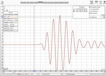
These measurement was made playing a (1) 1khz sinc (half a sine) in both main and sub channels while a mic was placed 15 cm from the main and and another mic was placed at the sub at the same distance. This was then recorded in stereo with my DAW. This is what is in the picture.
I think I omitted a LP on the sub as well. But as I use a 40 Hz LP on my sub I'm starting to suspect that this is not so good as the LP, once introduced, will indeed introduce delay...
Tricky tricky...
Thanks fluid - I'll check into your suggestions!
//
Maybe output optimisation on max is an other way?
I'll try and explain my second way of aligning in pictures. It's quite easy once you get the hang of it.
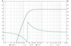
Let's say we have a sub with a LR24 at 160 Hz:

In this example I've added delay of 10 ms, this is an IIR crossover, Linkwitz Riley 24. But in a timed measurement you could have a different number of delay, it does not matter as long as it is a measured true timing. (so use the timing method of your choice)
We want to align it with an array, also having a crossover at 160 Hz, to keep the example simple, it is a LR24 highpass.

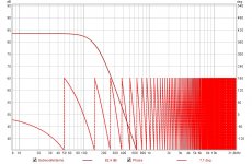
If we sum these measurements, it will not sum ideally, it shouldn't because we have more delay on one vs the other, but we also added an IIR crossover with it's own delay. Anyway, lets look at what the sum looks like:

Horrible, right? Not what we want at all.
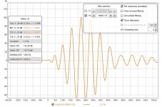
So what's next? We dive into the filters that are present in REW, and apply a 3rd octave filter at 160 Hz to the sub:

Setting the view to "%" shows us the waveshape, looks like what I've posted before, right?
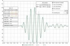
Doing the same on the timed measurement of the Array we get this:

Looking at the sum with the same filter applied gives us no hint at all:

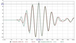
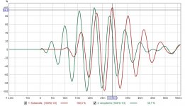
But if we look at the Overlay tab, and look at the filtered sub measurement and also make it show the filtered Array on the IR tab of the overlays:

See the shape of both the wave fronts? We need to align the largest peaks here. The crosshair is at the array peak here.
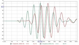
Now lets look up the largest peak of the sub's filtered wave shape:

Now all we need to do is determining the difference between both measured peaks. One is at 21.75 and the other is at 28.89 ms. So the difference here is 28.89 - 21.75 = 7.14 ms. Let's put that into our IR configuration tab. We advance the sub in this case, as I've put in 10 ms delay in the example as a start. But it really doesn't matter, we just need to align the peaks.

Here we advance the sub by the 7.14 ms difference we found in the overlays.
Another look at the Overlays, viewing the IR tab shows us the alignment:

Perfect alignment of the peaks! This should mean a sum would have to work too, but I'm on the max upload of pictures in this post 😀.
Let's say we have a sub with a LR24 at 160 Hz:
In this example I've added delay of 10 ms, this is an IIR crossover, Linkwitz Riley 24. But in a timed measurement you could have a different number of delay, it does not matter as long as it is a measured true timing. (so use the timing method of your choice)
We want to align it with an array, also having a crossover at 160 Hz, to keep the example simple, it is a LR24 highpass.
If we sum these measurements, it will not sum ideally, it shouldn't because we have more delay on one vs the other, but we also added an IIR crossover with it's own delay. Anyway, lets look at what the sum looks like:
Horrible, right? Not what we want at all.
So what's next? We dive into the filters that are present in REW, and apply a 3rd octave filter at 160 Hz to the sub:
Setting the view to "%" shows us the waveshape, looks like what I've posted before, right?
Doing the same on the timed measurement of the Array we get this:
Looking at the sum with the same filter applied gives us no hint at all:
But if we look at the Overlay tab, and look at the filtered sub measurement and also make it show the filtered Array on the IR tab of the overlays:
See the shape of both the wave fronts? We need to align the largest peaks here. The crosshair is at the array peak here.
Now lets look up the largest peak of the sub's filtered wave shape:
Now all we need to do is determining the difference between both measured peaks. One is at 21.75 and the other is at 28.89 ms. So the difference here is 28.89 - 21.75 = 7.14 ms. Let's put that into our IR configuration tab. We advance the sub in this case, as I've put in 10 ms delay in the example as a start. But it really doesn't matter, we just need to align the peaks.
Here we advance the sub by the 7.14 ms difference we found in the overlays.
Another look at the Overlays, viewing the IR tab shows us the alignment:
Perfect alignment of the peaks! This should mean a sum would have to work too, but I'm on the max upload of pictures in this post 😀.
Attachments
-
 Overlaytimed.jpg106.5 KB · Views: 279
 -
 Overlays IRsub.jpg116.2 KB · Views: 279
 -
 Overlays IR.jpg114.3 KB · Views: 280
 -
 Filteredsum.jpg136.9 KB · Views: 269
 -
 filtered IR.jpg134.9 KB · Views: 275
 -
 Filtered IR Sub.jpg149.6 KB · Views: 281
 -
 SumnotAligned.jpg104.8 KB · Views: 284
 -
 Array LR24.jpg102.2 KB · Views: 279
 -
 subwoofer LR24.jpg164.5 KB · Views: 292
 -
 Shift IR with Delay.jpg86.9 KB · Views: 467
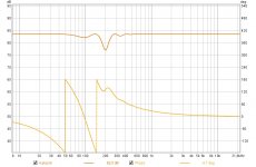
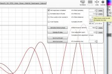
So lets look at the sum:

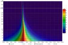
Nice and straight, right? Even when viewed in a Wavelet:

The slight curve we see is simply the phase rotation of a LR24 crossover.
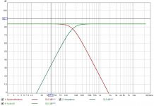
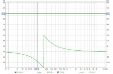
As confirmed when looking at the frequency and phase:

While this method might seem a little intimidating at first, it would ensure perfect alignment with basically all types of crossovers one could ever use, because we actually line up the actual waves with looking at it filtered right at the crossover. One caveat is that the Filtered IR frequencies limit us on where we can look at these wave shapes.

If one can live with that slight drawback, it probably is the easiest way to align two wave fronts perfectly, when measured at the actual listening spot with a good timing reference.
So if you can determine where you want to crossover, just use a spot that is available in that list of filtered IR's inside REW. Easy for me to say with such a wideband device as an array and a sub that can play up high. But if you can control where you want your crossover to be and the drivers can both do well at that point, it's a no brainer to get a perfect sum every time. Measured at the listening spot! Measuring up close and fantasizing about the perfect crossover at that point is just that, a fantasy. We want a good result where we're at, right? Not at some arbitrary distance because that way we gan gate the measurements better etc. All we need is a free wave front hitting the listening spot first and these wave shapes will still be recognisable enough to use this method.
It is way easier than I make it look here. Just clever use of the power a piece of software like REW gives us. All other methods seem quite complicated in comparison, as this will give a perfect fit every time. Be it linear phase crossovers or minimum phase or even asymmetric crossovers.
I hope this will give some of you inspiration to really use the tools we have available to us.
The hardest part is a simple subtract sum 😀. No determining of acoustic centers, and it even works if the crossovers aren't perfect.
Nice and straight, right? Even when viewed in a Wavelet:
The slight curve we see is simply the phase rotation of a LR24 crossover.
As confirmed when looking at the frequency and phase:
While this method might seem a little intimidating at first, it would ensure perfect alignment with basically all types of crossovers one could ever use, because we actually line up the actual waves with looking at it filtered right at the crossover. One caveat is that the Filtered IR frequencies limit us on where we can look at these wave shapes.
If one can live with that slight drawback, it probably is the easiest way to align two wave fronts perfectly, when measured at the actual listening spot with a good timing reference.
So if you can determine where you want to crossover, just use a spot that is available in that list of filtered IR's inside REW. Easy for me to say with such a wideband device as an array and a sub that can play up high. But if you can control where you want your crossover to be and the drivers can both do well at that point, it's a no brainer to get a perfect sum every time. Measured at the listening spot! Measuring up close and fantasizing about the perfect crossover at that point is just that, a fantasy. We want a good result where we're at, right? Not at some arbitrary distance because that way we gan gate the measurements better etc. All we need is a free wave front hitting the listening spot first and these wave shapes will still be recognisable enough to use this method.
It is way easier than I make it look here. Just clever use of the power a piece of software like REW gives us. All other methods seem quite complicated in comparison, as this will give a perfect fit every time. Be it linear phase crossovers or minimum phase or even asymmetric crossovers.
I hope this will give some of you inspiration to really use the tools we have available to us.
The hardest part is a simple subtract sum 😀. No determining of acoustic centers, and it even works if the crossovers aren't perfect.
Attachments
Last edited:
- Home
- Loudspeakers
- Full Range
- The making of: The Two Towers (a 25 driver Full Range line array)