Very cool, you're obviously having fun 🙂
And yeah, what's money when audio is ready to party with us 😀
And yeah, what's money when audio is ready to party with us 😀
I'm not saying it doesn't make sense, but that Octo DAC would leave me with two questions.
- Feeding it an input signal through USB, I have had problems with PC noise with 2 generations PC's ago and using a different amplifier than I have now.
- I don't know what it sounds like, and I do know I can be happy with the M1 (for now) as that has been tested and tried...
Shure, that said they in second or third generation of UAC2 chip now so much have happen including jitter is almost nader nowadys seen over at ASR site, only point for Okto myself is unhappy is miniDSP pulled their 10 channel Xmos card probaly because of competion so newer units than the tested one at ASR site has not the German Thesycon driver package for Xmos UAC2 chip which had nice adjustable ASIO driver, nowadays it live on WASAPI via Win10 native UAC2 driver or ASIO4all which should be good enough in think it wrap via Kernel streaming but would prefer a dedicated ASIO driver.
...Unless I would get an Okto in the mail to try/see if I like it, it simply is too big of a gamble for me despite it's crazy good numbers. That DAC8 Stereo Okto is out of this world crazy 😀.
Funny you say that because they have a unit touring EU requestable via email.
...I still see that Goldmund as a pretty crazy amp, powerful in its simplicity and philosophy...
Its not crazy but fantastic amp 🙂
...If I start anywhere, which I'm sure to do, the first step is probably known now. It may not end there 🙂...
No it may not end there and admit feel a bit guilty for that, on the other hand who asked, plus we probably have fun and learn a bit here and there, but with so much system units bonded one day you start a FFT stimulus window in REW RTA analyzer just listening without signal and find out all the stupid grass and mains noise that live in your chain especially the more one get downstream and especially for SE units, then you let it listen a pure sinus signal and if its real bad probably one can see the noisy ones from stimulus test have more small grassy stuff riding on sinus wave, then that Goldmund amp also get a differential upgrade and its audioable stuff for sensitive ears doing critical listening in mono one speaker at a time in say a HF shelve at whattever mild to hard correction sounds different even it shouldn't, much less forward on differential when system is complicated and more than simple stereo, also not that Chesky's Spanish Harlem is not a native forward recording but it gets much less annoying and soft on best as possible features from pro world is my opinion or experience.
I hear ya, BYRTT 🙂
As said, I probably will not be done after this step. But I'll get there in baby steps, one at a time 😉.
As said, I probably will not be done after this step. But I'll get there in baby steps, one at a time 😉.
Did your suspect USB system include RCA connectors? (rhetorical)
given our recent conversation, I was amused by this quote from the Okto user manual:
"Warning: we discourage from using balanced-to-unbalanced cables and converters. Doing so will result in a vastly decreased analog performance and may be also cause of groundloop induced hum issues. Unbalanced signal paths (e.g. widespread RCA) are unsuitable for device-to-device connections if high signal performance is desired, since they do not offer a separate path for equalizing ground loop currents that will naturally occur in a real-world
environment."
It has always seemed to me that the biggest challenge is extracting a pure analog signal from the noisy digital environment, be it on chip or on the PCB or both. One's best chance of doing that is with a balanced connection. Yes, one can connect RCA cables from the Xonar to balanced line receiver, floating the shield at the receiver, but if you don't do that, what is the real world SNR?
Of course I had to compare the Oktos 119 db SINAD to my MOTU's 112 db SNR.
I see the NC500 Ncore amp's SNR is below this at 1W output but well above it at high power. The noise stays the same, the output signal gets bigger. Some noise problems can be solved by power attenuators in front of the speaker to make the amp but out a bigger signal.
Even though this grass may be greener, there is a lot to be said for finishing out the path you are on before starting off again with a new device. Time enough to do that later...
Last edited:
As you seem pretty determined to go with Tom's Buffers one thing to consider before you get them is if you want any gain to be configured in the buffers themselves.
Changing SMD resistors of the type Tom is using on a board with a ground plane really needs to be done with a hot air rework station. Trying to do it with two soldering irons is quite likely to result in a damaged board. I know because I destroyed a First One Module trying to avoid buying the proper hot air gun.
In the past Tom has been willing to change a resistor or two prior to purchase.
With a couple of through hole resistors it is pretty easy to make a voltage divider to reduce it down after if it turns out you got too much.
nc535, balanced equipment properly built to the AES standard is clearly the best way to connect audio devices, no doubt. In the real world not all devices use those and in some cases more harm can be done to the signal trying to make it balanced because "balanced is better" than just leaving it alone. Using a pseudo balanced cable to connect a single ended output to a balanced input works well enough. A lot of professional equipment runs single ended through it's main signal path and is balanced or unbalanced where needed so it is not always as easy as looking at the connectors on the outside if ultimate signal integrity is desired.
Last edited:
I hear ya, BYRTT 🙂
As said, I probably will not be done after this step. But I'll get there in baby steps, one at a time 😉.
...😀 great some day we are maybe there.
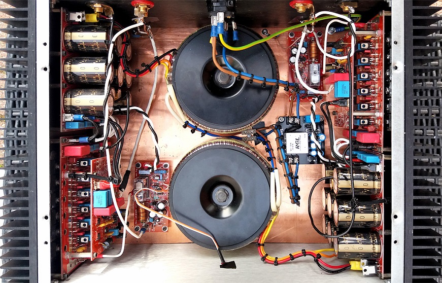
Tom has answered email from this morning, in first line he start comment on Goldmund clone because of the two pictures of amp incert to email, we talked Danish there and directly translated using Google he wrote QUOTE: It was quite something of an amplifier !! Nicely made UNQUOTE, so think hold on koldby and wesayso you should be proud.
Voltage for buffer 1 volt in -> 1 volt out whether its SE or differential and adjustable gain via resistors, but that one you knew can i see in your PM minuttes ago, thanks.
Then there's the answer for possibility mounting buffer inside Telos clone down the road translated from Danish using Google he wrote QUOTE: I have no qualms about mounting Universal Buffer in the cabinet you are displaying. I want to keep it from the rectifiers and electrolytes in the power supply (1st priority). I would also keep it away from the wires going off the ring cores if possible (2nd priority). The currents in the rectifier and in the transformer in / out wires are not "neat" (~ 100 + A pulses !!) so they can easily plug into sensitive circuits. Even a few cm distance is worth gold here. UNQUOTE.
Last edited:
As you seem pretty determined to go with Tom's Buffers one thing to consider before you get them is if you want any gain to be configured in the buffers themselves.
Changing SMD resistors of the type Tom is using on a board with a ground plane really needs to be done with a hot air rework station. Trying to do it with two soldering irons is quite likely to result in a damaged board. I know because I destroyed a First One Module trying to avoid buying the proper hot air gun.
In the past Tom has been willing to change a resistor or two prior to purchase.
With a couple of through hole resistors it is pretty easy to make a voltage divider to reduce it down after if it turns out you got too much.
nc535, balanced equipment properly built to the AES standard is clearly the best way to connect audio devices, no doubt. In the real world not all devices use those and in some cases more harm can be done to the signal trying to make it balanced because "balanced is better" than just leaving it alone. Using a pseudo balanced cable to connect a single ended output to a balanced input works well enough. A lot of professional equipment runs single ended through it's main signal path and is balanced or unbalanced where needed so it is not always as easy as looking at the connectors on the outside if ultimate signal integrity is desired.
Tom has thought about that, gain is set with through hole resistors so end user can determine and change gain at will. Smart thinking!
Good to know, SMD resistors are easy enough to solder on with an iron not so easy to get off 😉
...😀 great some day we are maybe there.
Tom has answered email from this morning, in first line he start comment on Goldmund clone because of the two pictures of amp incert to email, we talked Danish there and directly translated using Google he wrote QUOTE: It was quite something of an amplifier !! Nicely made UNQUOTE, so think hold on koldby and wesayso you should be proud.
Voltage for buffer 1 volt in -> 1 volt out whether its SE or differential and adjustable gain via resistors, but that one you knew can i see in your PM minuttes ago, thanks.
Then there's the answer for possibility mounting buffer inside Telos clone down the road translated from Danish using Google he wrote QUOTE: I have no qualms about mounting Universal Buffer in the cabinet you are displaying. I want to keep it from the rectifiers and electrolytes in the power supply (1st priority). I would also keep it away from the wires going off the ring cores if possible (2nd priority). The currents in the rectifier and in the transformer in / out wires are not "neat" (~ 100 + A pulses !!) so they can easily plug into sensitive circuits. Even a few cm distance is worth gold here. UNQUOTE.
So it can be done if we stay clear of a few features that could disturb the circuit...
So it can be done if we stay clear of a few features that could disturb the circuit...
Yes that is the message and good to know, but in that power amp is a grain of gold in sound and value suggest should you ever do the surgery suggest when all the stuff are mounted then for first fireup power only up buffer circuit and loop its output outside with some flying wires and measure its output for any DC potential with DMM set to milivolts, if that is okay let buffer play to some dirty cheap or used amp for half a hour or so and dangle gently to board and box a few times while listening there ain't any unstability anywhere, if okay route buffer output to power amp and enjoy. The stupid oversafety first run is because Telos Clone is pure DC coupled and even it probably has fail sensors and safety upstart circuit it takes nothing but a microsecond to break pure DC coupled power amps which we couldn't bear for this one, and yes have a laugh myself has broken several Sansui amps because of DC thumps on 250mVolts sensitive input frontend that tell the backend to amplify pure DC signal to potential more than supply rails, connected woofers can look weird if any output transistors dont break down their life in open condition and feed one full DC rail potential to transducer.
Last edited:
Wow, lets first do the save mod then 🙄😱😀
Yes 🙂...
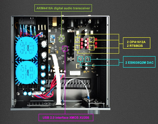
Also in you a magician in metal and weldering it can not hurt make some pratical iron screen for buffer as for example is seen in below Soncoz DAC at left side surrounding PSU area, its not much but helps probably isolate bit more than nothing.
Attachments

I am not nearly as intelligent as most of you, and I was wondering if I could pose a few questions regarding the signal chain, your worries and the solutions.
First of all; as I was thinking about having my own signal chain it was something along the line of;
1. JRiver and all those things using corrections, using a similar approach to Wesayso. That signal would be transferred digitally (well, via USB with all the caveats and philosophical pondering of what is a truly digital signal) to a DAC. As I was thinking about this, the output to the DAC would be at a fixed level, which would encompass the 20-30dB adjustments needed for the TC9FDs. JRiver has a 64bit engine for processing which would be enough for a perfect volume control and the FIR-magic. (Question about this later).
2. The DAC would be passing out the signal at full volume. No extra attenuation, hopefully no filters, nothing. It would just act as a industrial-type-DAC. The analogue signal would then be balanced via XLR to my magical little Chinese AMP of some 250watts. That particular amp has a volume control (which I hope is analogue). I could therefore adjust the listening level manually - hopefully not exceeding a dozen or so watts.
3. The fanciest of all speaker wires, forged from an ancient asteroid, blessed by popes and shamans and what not, to the speaker terminals.
4. From the speaker terminals it would travel along badly soldered and a tangled mess of supposedly series-parallel mess of a DIY madness.
5. All the magical steps of converting electrical impulses to magnetic energy, moving "cheap TV drivers with plastic" moving air and so on and so forth.
This is, in my simplicity, how I am going about things. Reading the last few days of posts here I gather that we are questioning a few things in Wesayso's chain (well he is).
What I do not quite understand is why there is a headroom problem. As I see it, the software could modify the signal, digitally in 64 bits (grains of sands on all the beaches) and have the DAC output a voltage which could drive the amp to it's full potential.
I am very sorry for my lack of understanding; but can you explain to me, like I was 12 years old, where the headroom problem exists and why - and in that way explain to me where such a problem would exist in my over ambitious build?
(I will start a new thread with my build when live get's out of the way of fun)
(I have read all of the threads here on Line Arrays, most of which I read daily - but as a re-read each of them my understanding gets better).
That's a loaded question as can be seen by the discussion we've had about it.
For me, on two different configurations I have noticed a clear difference.
What I mean by that is that lowering the (average) output of the DAC of the musical signal, so there is room left for the peaks that hit above that average and applying the gain stage after the DAC, in the form of a pré amp to make up for the amount we lowered it, makes the music sound more dynamic.
It does not sound particularly bad without these steps, but a bit more forced.
Not unlike lots of music out there today which has a (these days often severely) limited dynamic range.
In search for better believability of the musical experience I see it as a step up. If you haven't heard the difference, I could believe you'd never notice it and be quite content with what you have.
However, for me personally I do believe it is best to keep some head room for every signal at every point in the chain.
I do like the way Tom described his experience and that thread has more than one post where he tries to convey his view.
I also like how mark100 described his point of view here, the limit of what I will allow for in headroom is limited by the room in bits I have. In this light I do think that an analog volume control is quite a good move, where quite a while ago I wasn't that convinced about that. I won't move towards that immediately but may do so in the near future. Most of my listening sessions are at a fixed listening level based on the average levels as determined by JRiver. For movies I mostly use the same level too, but movies tend to be more alike in their averages as they do have some good basic rules set to achieve that.
The EQ we apply for arrays eats away from internal headroom, no good way around that, except if we would move the large boost/cut parts of that desired EQ curve outside of the digital domain and only do the little tweaks with DSP in the digital realm. That could probably make up a good solution. Granted that even in that solution it remains important that the parts that follow the (analog + digital) EQ, such as the amplifier, can handle what it gets offered.
It is easier to make a system play a sine wave perfectly at a desired level than the odd signal that represents a musical piece. Where mid and high notes ride along on top of the bass sine movement in that signal. In an ideal situation the speaker drivers can follow that input signal perfectly. Such drivers don't really exist. But we 'should' be able to get the electrical signal that feeds them as close to perfection as we can. What it takes? I don't know exactly... but it does seem to point out that as much headroom as you can allow helps to get there.
Which to me means using big enough amplifiers backed up with beefy power supplies etc. And looking closely at what happens in that small signal stage as well.
It is easy to produce a 85 dB average at the listening spot. It is a lot harder to make sure you can also produce the peaks above that average faithfully. This is a challenge for the drivers used as well as it is for the electrical components that go before it.
It takes a lot more power to play a dynamic recording correctly than it takes to play a compressed one.
Read the posts by Tom Danley in this thread, that should give you something to think about. You can use the "search this thread" option and with the advanced search option use his name in the: "Search by User Name" box.
Last edited:
Yes 🙂...
Also in you a magician in metal and weldering it can not hurt make some pratical iron screen for buffer as for example is seen in below Soncoz DAC at left side surrounding PSU area, its not much but helps probably isolate bit more than nothing.
If (or when) I decide to go that route I will mount the Universal Buffer within its own case high above those toroids. Which is best, I do have some small cases that should fit the buffer. Is Aluminium good enough? The in and output would be from the sides of that case free and far removed from the toroids straight to the back.
There are two simple reasons why some DAC's perform better with some attenuation built in if you can live with the level reduction.What I do not quite understand is why there is a headroom problem. As I see it, the software could modify the signal, digitally in 64 bits (grains of sands on all the beaches) and have the DAC output a voltage which could drive the amp to it's full potential.
I am very sorry for my lack of understanding; but can you explain to me, like I was 12 years old, where the headroom problem exists and why - and in that way explain to me where such a problem would exist in my over ambitious build?
The article above on intersample peaks gives a good visual explanation of one issue. It is possible for a peak exceeding 0dBFS to be encoded digitally. When converting this back to analog it clips even if for only a very short time. This can be audible but may be hard to put your finger on exactly what the issue is. The meters may not show the clipping. Digitally reducing the input level to the DAC by 4dB fixes this in almost every conceivable situation. Some DAC's don't suffer from it like the latest Benchmark DAC's, a lot still do.
The second reason is that most DAC's do not perform at their best at 0dB, they are better behaved a few dB below, they measure better at that level.
This is where some "headroom" in the digital system allows the DAC to perform better than without it.
Headroom in an analogue system whether pure voltage in a line stage or voltage and current in a power amp is about making sure the dynamic range of the input signal can be reproduced without clipping or compressing.
If (or when) I decide to go that route I will mount the Universal Buffer within its own case high above those toroids. Which is best, I do have some small cases that should fit the buffer. Is Aluminium good enough? The in and output would be from the sides of that case free and far removed from the toroids straight to the back.
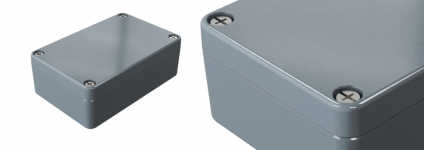
Sounds good high above : ) with a case but think cheap even some scrap steel thick as possible or is it copper that is better if magnetic fields is the interference, maybe below alu box RS components number 506-918 could be mounted outside on back of amp in its only 34mm deep and 98x64mm for rest, buffer is 60x65mm so with a little luck PCB and 2x XLR or 2x TRS jack inputs can be squized into it, buffer output channels via a short wire and plugged into existing RCA plugs and PSU for buffer inside big existing big power amp box.
Attachments
Last edited:
Thanks fluid,
I have to read up on what Mu metal is but admit seen some members here and there mention that word, myself is hot on the look of copper here and there used for audio gear as wesayso posted few pages back
Can't stop love that look 😀
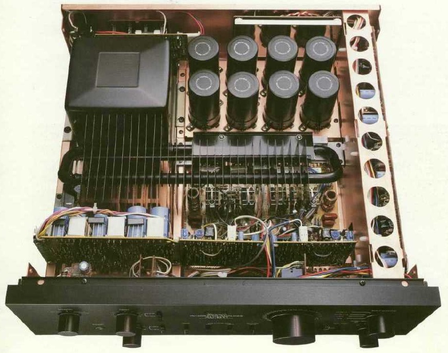
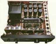
Have two 0,003% relative low distortion 95 watts Sansui AU-D9 myself and bit funny they have feed forward circuit feature on the big Sanken output transistors, feed forward is one of Bench Mark's features nowadays on their more than nice specification numbers , got the first AU-D9 brand new back in 1983 and it was a little brother to their flagship 130 watts AU-D11 seen below, look that lovely copper there mine hasn't got that other than mine is as good local shielded as flagship if you look how RCA I/O PCB behind lytic banks plus two big PCB (Phono pre-MM-MC/riaa) at right side is local shielded with metal.
I have to read up on what Mu metal is but admit seen some members here and there mention that word, myself is hot on the look of copper here and there used for audio gear as wesayso posted few pages back
Can't stop love that look 😀
Have two 0,003% relative low distortion 95 watts Sansui AU-D9 myself and bit funny they have feed forward circuit feature on the big Sanken output transistors, feed forward is one of Bench Mark's features nowadays on their more than nice specification numbers , got the first AU-D9 brand new back in 1983 and it was a little brother to their flagship 130 watts AU-D11 seen below, look that lovely copper there mine hasn't got that other than mine is as good local shielded as flagship if you look how RCA I/O PCB behind lytic banks plus two big PCB (Phono pre-MM-MC/riaa) at right side is local shielded with metal.
Attachments

Last edited:
- Home
- Loudspeakers
- Full Range
- The making of: The Two Towers (a 25 driver Full Range line array)