Hi PatrickImportant is he likes it, not me.
But you can build another pair and do AB test against the Toshiba's (and/or IRFP's), just for fun.
Won't cost you a fortune.
Patrick
Yes, sound is a personal taste and there is no final judgment.
i guess that the measurements are "okay" otherwise you will give Harry a sign.
i owned 30 years a Accuphase C200V and P300V and i know what you mean....after FW M2/F5 lateral and other source an LS the P300V was sold.
thank you for your information.
There is a new version of the M2OPS designed to go together with the F5Preamp, NOT with an opamp as published.
The F5Pi project is not yet ready for publication, waiting final integration and independent audition.
So for now you can use the Gerber as published here and use by all others.
I have no knowledge and therefore comments about any M2/M2X PCBs that exist.
Patrick
The F5Pi project is not yet ready for publication, waiting final integration and independent audition.
So for now you can use the Gerber as published here and use by all others.
I have no knowledge and therefore comments about any M2/M2X PCBs that exist.
Patrick

I have 5 sets of boards to give away (shipping also free). They are fully through-hole and UMS compatable. The feedback resistor positions are terminal block compatable so you can change them out easily. PM if interested. US only. With a few days of listening, local might edge out mixed for me. I might try different values for the mixed
interested tooCan you please help me with a direct link to F5Pi--thx
Harry
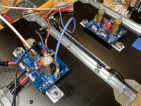
Some progress on my M2OPS rebuild.
Ready for chassis assembly 😉
- Bias current was a bit too high at 1.45A with 0R56 source resistors, increased them to 0R62.
- Running OPA604 on the edge with +/-23.5V PSU, Rs resistors increased to 68R for an additional 0.38V reduction.
- Setup for mixed feedback.
- Toshiba 2SK3497/2SJ618 installed
- Cooked each channel on the bench for 1Hour = 1.33A bias current, 1mV offset
Ready for chassis assembly 😉
Attachments
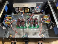
What kind of terminals for the VOut, Vs Gnd etc. are you using? I'm Not happy with my Alu screw solution...Some progress on my M2OPS rebuild.
- Bias current was a bit too high at 1.45A with 0R56 source resistors, increased them to 0R62.
- Running OPA604 on the edge with +/-23.5V PSU, Rs resistors increased to 68R for an additional 0.38V reduction.
- Setup for mixed feedback.
- Toshiba 2SK3497/2SJ618 installed
- Cooked each channel on the bench for 1Hour = 1.33A bias current, 1mV offset
Ready for chassis assembly 😉
Since Mark mentioned a discrete frontend in post #10, maybe it's good to show an example.
Not fully optimised yet, but in principle it works.
But one at a time.
View attachment 1095560
Patrick
What is the part number
Well, it is making music. 🙂
Opamp is OPA551, in local feedback (excluding the M2OPS, post #26).
Yet DC offset is totally stable.
R13,14 should be at least 0R56, maybe even 0R62.
View attachment 1106454
Patrick
What is the part number of GND, +Vs connectors?
I want to use these part.
Standard M3x8 or M4x8 brass standoff's.
Best not nickel (magnetic) plated, just blank brass.
Brass screws at the bottom side of the PCB.
Both sides soldered; you will need 200W soldering iron.
Patrick
Best not nickel (magnetic) plated, just blank brass.
Brass screws at the bottom side of the PCB.
Both sides soldered; you will need 200W soldering iron.
Patrick
Cheap start for a amazing amp.. Sounds promising open wide.........DC Offset lower as 2mV, bias 1,55A

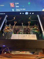
Nice build. What kind of SMPS is it?M2OPS Rebirth is complete!
The 1.33A bias current works well in this 4U 300 modushop chassis, sinks never get above 48°C with ambient temp of 22°C.
- Home
- Amplifiers
- Pass Labs
- The M2 Output Stage in Class A/B, and maybe a Power WHAMMY?