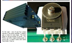
Some of the reviews of production First Watt amps (fully assembled and tested units, sold to paying customers) on the "6 Moons" review site, show Fairchild power transistors in the output stage.
Maybe you can see something I cannot ?
https://6moons.com/audioreviews/firstwatt11/m2_2.html
Patrick
https://6moons.com/audioreviews/firstwatt11/m2_2.html
Patrick
And some examples of 2SK3497/2SJ618 in Accuphase power amps.
http://www.highendnews.info/reviews/Accuphase_E-530_en.htm
https://www.accuphase.com/cat/e-560_e.pdf
https://www.accuphase.com/cat/a-65_e.pdf
https://www.accuphase.co.jp/cat/a-47.pdf
https://hi-fi.com.pl/testy/końcówki-mocy/4076-accuphase-a-47.html#
https://www.audioshark.org/accuphase-168/accuphase-m-6200-a-6729.html

Patrick
http://www.highendnews.info/reviews/Accuphase_E-530_en.htm
https://www.accuphase.com/cat/e-560_e.pdf
https://www.accuphase.com/cat/a-65_e.pdf
https://www.accuphase.co.jp/cat/a-47.pdf
https://hi-fi.com.pl/testy/końcówki-mocy/4076-accuphase-a-47.html#
https://www.audioshark.org/accuphase-168/accuphase-m-6200-a-6729.html
Patrick
Because Accuphase was mentioned, from the a-48_technical_information.pdf :
"The output impedance is decreased by 6 parallel push-pull
final stage arrangement of MOS-FETs.
Circuit configuration of the power amplifier engine is as same
as Class-A Stereo Power amplifier A-75.
A-48 features the new power MOS-FET device which is
heavy-duty and has the large rated current characteristic.
**Current capacity of power MOS-FET
A-47’s MOS-FET(Toshiba): 10A
A-48’s MOS-FET(Fairchild): 33A"
Attachments
When your previously chosen devices become obsolete, and you are forced to change, you will also need some nice story to tell your customers, not ?
I don't think I ever need 180W Class A into 2 ohm.
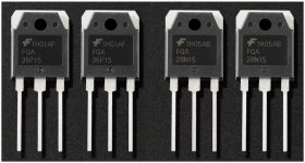
And of course those very nice and robust Fairchild MOSFETs have also been tested in the M2 OPS circuit (complementary follower) :
https://www.diyaudio.com/community/threads/complementary-power-mosfets.378024/post-6889027
🙂
Cheers,
Patrick
I don't think I ever need 180W Class A into 2 ohm.
And of course those very nice and robust Fairchild MOSFETs have also been tested in the M2 OPS circuit (complementary follower) :
https://www.diyaudio.com/community/threads/complementary-power-mosfets.378024/post-6889027
🙂
Cheers,
Patrick
Last edited:
Ha ha. Yes, maybe.Maybe he already have plenty of matched IRFPs ?
You need to ask him.
There is quite a bit of discussion recently about discrete frontends and Class A amps with low voltage (12V rails).
So I thought, how would the M2 OPS perform at such low voltages ?
First thing is that you need to use Toshiba MOSFETs, otherwise the Vgs of IRFPs will make you clip much earlier.
This is of course simulation only, but the results are real surprise.
Very low distortion all the way up to +/-10V output, and also up to 20kHz.
Just put an opamp (IC or discrete) upfront, use the mixed feedback loop, and the distortion will drop even further.
Now with 12V rails, the choice of opamp is enormous.
This M2 OPS is really amazing.
🤓
Patrick
Attachments

So why would I want to run my M2OPS at 12V, or anything between 12V and 24V ?
For the same dissipation (power supply VA, heatsink size, no. of MOSFETs, ....),
running at 12V means you can double the bias current to 2.5A.
And that would allow you to drive 2-ohm load.
For 4-ohm load, you can use 17V rails and 1.8A bias instead
It also means that you can reduce the values of the source resistors inversely proportional to bias current.
So you also reduce Zout in the process.
🤓
Patrick
Thanks Patrick. This will be perfect for driving the very efficient CD/horn part of my active 2-way speakers!
You can run this with the original schematics for 1.2A bias.
With 12V and say 8 ohm, you will just not be using all the current driving capability.
But it will work just fine, and runs cool (~30W per channel).
I am hoping one of the Alpha testers will run a quick test.
With opamp up front, you probably won't even need to trim DC.
But we'll see.
Patrick
With 12V and say 8 ohm, you will just not be using all the current driving capability.
But it will work just fine, and runs cool (~30W per channel).
I am hoping one of the Alpha testers will run a quick test.
With opamp up front, you probably won't even need to trim DC.
But we'll see.
Patrick
I ran some preliminary tests on my M2OPS build. I had been running this at +/-28V from a pair of SMPS300re in my test chassis for quite a while. So I took it out to the workshop and hooked it up to the bench supply putting out +/-12V - one lab supply for each channel as my supplies arelimited to 2A per rail.
I'm seeing 1.05A per rail draw, which is a bit lower than with 28V - EUVL will pop along to explain why - I didn't do any adjustments in changing the supply, literally just pulled the connectors from the SMPS and connected to the lab supplies. DC offset was similar to 28V - it starts at maybe 100mV or so, and drops as it all heats up. With 12V this was still dropping but slower as the bias was lower. I reckon if bias was the same, offset wouldn't even need to be adjusted.
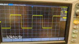
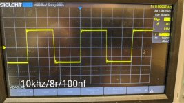
Square waves at 10kHz attached below - there is a little more ringing with the capacitive load at 12V compared to 28V.
Subjectively, just on workshop speakers, laptop playing youtube music, sound signature is the same, very clean, nothing audibly wrong. Pretty amazing really.
I'm seeing 1.05A per rail draw, which is a bit lower than with 28V - EUVL will pop along to explain why - I didn't do any adjustments in changing the supply, literally just pulled the connectors from the SMPS and connected to the lab supplies. DC offset was similar to 28V - it starts at maybe 100mV or so, and drops as it all heats up. With 12V this was still dropping but slower as the bias was lower. I reckon if bias was the same, offset wouldn't even need to be adjusted.
Square waves at 10kHz attached below - there is a little more ringing with the capacitive load at 12V compared to 28V.
Subjectively, just on workshop speakers, laptop playing youtube music, sound signature is the same, very clean, nothing audibly wrong. Pretty amazing really.
Attachments
The bias reduction is easy to explain.
Refer to the schematics in post #20.
The current through the photo-transistor of the optocoupler is reduce by 2.5x when lowering from 28V to 12V rails.
That also means that less current is required at the optocoupler LED, which is driven by R13,14.
Hence reduced bias.
To restore bias, one can change R6,7 to 20k instead.
The slight increasing in capacitive load ringing is also due to reduced Vds, which increases MSFET capacitances.
But it is really not much ringing with an unrealistic capacitive load.
So 12V works. 🤓
Patrick
Last edited:
I’ve had the teabag M2 boards and Harris Fets for some time- trying to clear some time to build. I’ve been experimenting with different preamps these days so was thinking to just use the M2 output section as this thread describes.
What I haven’t seen discussed (or maybe I missed it) is what is the performance of this circuit with a lower bias point? I realize I lose some class A current driving capability, but for 8 ohms, what kind of distortion performance are we talking if we drop bias to 1A or .75A.
F4 is .43 after all. I know it’s three parallel devices, but the fact that it’s 3 shouldn’t affect the typical 1W or even 5W measurement, should it?
The only way to find out is to build and try.
You have boards and devices, so what is stopping you ?
You can always turn it back up if you don't like low bias.
🤓
Patrick
You have boards and devices, so what is stopping you ?
You can always turn it back up if you don't like low bias.
🤓
Patrick
Yes of coarse, but it’s a long process for me. Before buying heatsinks, assembling all the parts etc wondering if anyone has already at least partially explored this terrain. Surprising if not, considering how many have built the M2.
I just finished an amp about two months ago. Need some downtime to enjoy this one, but also gathering ideas for the next 🙂
I just finished an amp about two months ago. Need some downtime to enjoy this one, but also gathering ideas for the next 🙂
- Home
- Amplifiers
- Pass Labs
- The M2 Output Stage in Class A/B, and maybe a Power WHAMMY?