Hello Patrick, any further updates on the announced Toshiba quads you mention testing in post #76 on the 19th November?
The sample pair of MOSFETs left for Canada on 26 Nov.
Canadian Post is not giving tracking information.
So we all need to wait.
But you should first build and listen with IRFPs.
Only cost you a few USDs.
Patrick
Canadian Post is not giving tracking information.
So we all need to wait.
But you should first build and listen with IRFPs.
Only cost you a few USDs.
Patrick

Thanks Patrick, I am actually doing that right now with pcb,s delivered last week from JLCPCB, just matching some IRFP's right now. Waiting on some components ordered 2 days ago from Mouser - should be here next week.
Will keep an eye on the thread, thanks again.
Will keep an eye on the thread, thanks again.
It is meant to be a fun project to try out different configurations with little expenses.
And when you are totally happy with it, then you can consider going to more expensive devices.
There is more fun to do it that way, then just to go to the "end" in one step.
Any maybe we'll also release the discrete frontend later, when it is fully tested.
So just enjoy the journey.
Patrick
And when you are totally happy with it, then you can consider going to more expensive devices.
There is more fun to do it that way, then just to go to the "end" in one step.
Any maybe we'll also release the discrete frontend later, when it is fully tested.
So just enjoy the journey.
Patrick
some progress but stalled as I didn't order enough onboard caps ( or as it turns out surface mount 1418 diodes ( i have a boatload of through hole so am going to rig them up instead ) )

I would just build one and get it to work first before building the other 3.
Also you might want to leave at least 1mm between the power resistors and the PCB.
At least that is what I do.
Also are you going for local / global / mixed feedback ?
Please read carefully how the configurations are different, which components to populate, and what values to use.
https://www.diyaudio.com/community/...-and-maybe-a-power-whammy.390636/post-7177569
https://www.diyaudio.com/community/...-and-maybe-a-power-whammy.390636/post-7189861
Patrick
Last edited:
There is a small gap under the resistors, but likely not enough for effective air flow.
I set it up with mixed feedback and a removable primary feedback resistor.
I set it up with mixed feedback and a removable primary feedback resistor.
I mentioned in post #76 that we have a new batch of matched Toshiba 2SK3497 / 2SJ618 to offer.
https://www.diyaudio.com/community/...-and-maybe-a-power-whammy.390636/post-7179541
But we did not want to offer them until they have been measured in circuit.
Twitchie kindly agreed to do this again, as he did the previous time, to make sure we used identical setup.
https://www.diyaudio.com/community/threads/complementary-power-mosfets.378024/post-6889027
I am happy to say that we can demonstrate that the previous results are repeatable.

To quote Twitchie himself:
"Initial result:
THD 0.00325%, H2 -0.00076% or -102.4dB, H3 0.0031% or -90.1dB
Bias 1.31A with 0R62 3W resistors for R13/14 without any trimming
Input signal -13dBV on QA402 for 1.1W.
-14dBV outputs 0.9W with 0.0029%THD.
So safe to say 0.003% at 1W into 8R."
Compare to IRFP's H2 -83.2dB & H3 -85.2dB in post #50:
https://www.diyaudio.com/community/...-and-maybe-a-power-whammy.390636/post-7172450
We'll arrange a GB for the 30 matched quads available in January, to avoid Christmas postal traffic.
Cheers,
Patrick
https://www.diyaudio.com/community/...-and-maybe-a-power-whammy.390636/post-7179541
But we did not want to offer them until they have been measured in circuit.
Twitchie kindly agreed to do this again, as he did the previous time, to make sure we used identical setup.
https://www.diyaudio.com/community/threads/complementary-power-mosfets.378024/post-6889027
I am happy to say that we can demonstrate that the previous results are repeatable.
To quote Twitchie himself:
"Initial result:
THD 0.00325%, H2 -0.00076% or -102.4dB, H3 0.0031% or -90.1dB
Bias 1.31A with 0R62 3W resistors for R13/14 without any trimming
Input signal -13dBV on QA402 for 1.1W.
-14dBV outputs 0.9W with 0.0029%THD.
So safe to say 0.003% at 1W into 8R."
Compare to IRFP's H2 -83.2dB & H3 -85.2dB in post #50:
https://www.diyaudio.com/community/...-and-maybe-a-power-whammy.390636/post-7172450
We'll arrange a GB for the 30 matched quads available in January, to avoid Christmas postal traffic.
Cheers,
Patrick
Last edited:
How devices sound is very subjective and circuit dependent.
So it is perhaps not very informative to post sonic impressions.
But this Japanese DIYer compared BJTs to Darlingtons to 2SK3497/2SJ618 in his circuit.
http://www9.wind.ne.jp/fujin/diy/audio/dora/dora.htm
And this is what he said :
2SA1939/2SC5196
The outline is slightly sweet and quiet sound quality.
The lingering vibes are pleasant, probably because it sounds a little echoed.
The atmosphere of moist vocals is excellent.
The volume of the low range is sufficient, but the bass feels a little sluggish.
2SB1557/2SD2386
There is almost no difference from 2SA1939/2SC5196.
Because it is a Darlington connection, I thought that the gain would increase and the input sensitivity would increase.
But I was disappointed.
2SK3497/2SJ618
Clean and crisp sound.
The low range is also tight, and there is no dull place.
The midrange is a little stiff and the vocals may be slightly "sexy".
But I don't feel the "dramatization" like 2SA1939/2SC5196.
It's the best of the three types, so I finally decided to use this one.
One cannot use BJTs in the M2 Output Stage unless an additional mosfet driver stage is added.
Patrick
You want to use it as a headphone amp ?
It is a bit over the top with >100W power consumption ?
🙂
Patrick
It is a bit over the top with >100W power consumption ?
🙂
Patrick
Yeah, because I read it can replace output Whammy, which was headphone amplifier.You want to use it as a headphone amp ?
It is a bit over the top with >100W power consumption ?
🙂
Patrick
It has a very similar topology as the WHAMMY but can use used to drive speakers.
That is what we meant by power WHAMMY -- a WHAMMY type power amp for speakers.
Patrick
That is what we meant by power WHAMMY -- a WHAMMY type power amp for speakers.
Patrick
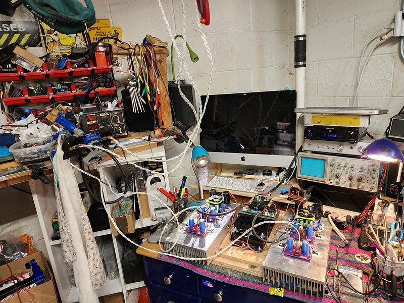
short progress update :
 M2OPS working
I have built up the boards and mounted them to the heatsinks with a capmx per channel , rails are sitting at 23.45V under load , bias is about 1.1A with 0R68 output resistors
both channels behave identically and the heatsinks sit at 45deg C after about 30 min
not hooked up to speakers or a source yet, that is the next step
Thanks Patrick - this has been fairly smooth sailing thus far.
..dB
M2OPS working I have built up the boards and mounted them to the heatsinks with a capmx per channel , rails are sitting at 23.45V under load , bias is about 1.1A with 0R68 output resistors
both channels behave identically and the heatsinks sit at 45deg C after about 30 min
not hooked up to speakers or a source yet, that is the next step
Thanks Patrick - this has been fairly smooth sailing thus far.
..dB
All hooked up run for an hour to make final offset adjustments before hooking up the input and speakers - using XRKs SE/BAL input card
start up is thump free, small turn off thump but minimal, no noise at the speakers without music - true absence of sound - deathly quiet
my signal generator is on the blink so just tested for sound - crisp, clear and full bodied. Very promising despite the beat up bose 201 testbed
now to my least favourite part of DIY - making a chassis
..dB
- Home
- Amplifiers
- Pass Labs
- The M2 Output Stage in Class A/B, and maybe a Power WHAMMY?