taisho_daniel,
Thank you for pointing this out. I thought I had read it earlier but dint know where. Well, need to read more, thanks anyway.
Thank you for pointing this out. I thought I had read it earlier but dint know where. Well, need to read more, thanks anyway.
I did not find the time to research why my build needs such a high value cancelation resistor but i solved another problem that bugged me since i build the first version :
Sometimes the buffer works and sometimes not !
No matter what i did : silence !
That really drove me nuts. Two days ago again i could not get any sound out of the buffer although it had worked fine the other day.
On the bench it tapped the TKD pot and here we go : the pot has a mechanical deffect on both channels. I bend the pot a little bit and got it working. Maybe that was the problem that Self found. The TKD seems to be quite delicate and may not like strong misuse like i do sometimes when i test worst case.
Well, i do not want to bad mouth TKD. It is a very smooth and precise part, better then the Blue Alps i think and this is the first time i had that problem so it is not typical.
Sounds like oscillation
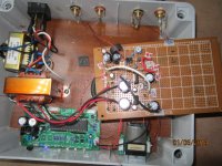
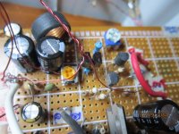
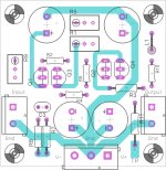
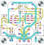
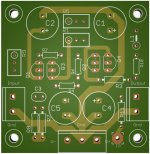
I build one channel with point to point. in fact this is the secong build point to point and both have very similiar problems.
the circuit is from the keantokean blog page as stated in the beginning of the thread.
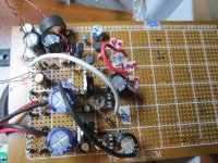
There is a constant hump that increases with volume and changes when the input leads and volume control are touched.
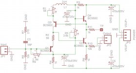
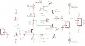
Power supply is with 2 LM 317. output V is +/- 10V.
Transistors are BC 550 c and 560c. Different brand . R1 , R2 are both 56 R.
Vbe at Q3 is 61Mv. Vbe at Q4 is 68 Mv. Tp measure 5 v after trimming.
Output offset is 6 mv .
Hearing through the humming, the sound is very good and no obvious distortion.
Any suggestions to solve the humming sound.??
Anyway to troubleshoot without analayser. ??
Do i need a gate stopper at Q1?
could be the Inductor --wrong spec ?? . i salvage this from somewhere and is this value critical ?? the previous version is self wound ---15 turns over a AA battery .
I am building this to power a class D amp with an input impedance of about 10 K. This amp has too much gain and hence i have a voltage divider before the volume control. The remote for the volume is bought from ebay .
please excuse for an untidy build.
cheers
kp93300
I build one channel with point to point. in fact this is the secong build point to point and both have very similiar problems.
the circuit is from the keantokean blog page as stated in the beginning of the thread.
There is a constant hump that increases with volume and changes when the input leads and volume control are touched.
Power supply is with 2 LM 317. output V is +/- 10V.
Transistors are BC 550 c and 560c. Different brand . R1 , R2 are both 56 R.
Vbe at Q3 is 61Mv. Vbe at Q4 is 68 Mv. Tp measure 5 v after trimming.
Output offset is 6 mv .
Hearing through the humming, the sound is very good and no obvious distortion.
Any suggestions to solve the humming sound.??
Anyway to troubleshoot without analayser. ??
Do i need a gate stopper at Q1?
could be the Inductor --wrong spec ?? . i salvage this from somewhere and is this value critical ?? the previous version is self wound ---15 turns over a AA battery .
I am building this to power a class D amp with an input impedance of about 10 K. This amp has too much gain and hence i have a voltage divider before the volume control. The remote for the volume is bought from ebay .
please excuse for an untidy build.
cheers
kp93300
Attachments
Last edited:
Can you set the voltmeter to AC and probe across the rails? And then probe across the input and output of the Kuartlotron to see if you can measure the hum directly, so see exactly where it's occurring.
Can you set the voltmeter to AC and probe across the rails? And then probe across the input and output of the Kuartlotron to see if you can measure the hum directly, so see exactly where it's occurring.
thanks keantoken.
i will do that tonight as i am at work now
Don't probe from the input to output, probe from input to ground and output to ground. In case you misunderstood.
Input to ground--0v ac
outout to ground about 0 v ac
Power supply --Gnd to positive shows 21v ac !!
Power supply -- gnd to negative show 0 v ac.
i am now checking the power supply
thanks keantokean.
outout to ground about 0 v ac
Power supply --Gnd to positive shows 21v ac !!
Power supply -- gnd to negative show 0 v ac.
i am now checking the power supply
thanks keantokean.
Am considering trying this as the buffer between a Soekris DAC's unbuffered output - which is 625R and 1.4Vrms - and a Class D amp whose input impedance is 2200R.
Can I use +/-15V or is that too high?
Can I use +/-15V or is that too high?
There's no audio device that doesn't have an optimal voltage. And that wasn't it.Can I use +/-15V or is that too high?
I would not increase the voltage, because self-heating effects are proportional to Vce. All the resistor values would also need changed. The transistors here have exceptional low-Vce behavior, so the input voltage should not be more than necessary.
A resistor and TL431 shunt regulator would be the simplest way to reduce the rails and fully meet the Kuartlotron's needs.
A resistor and TL431 shunt regulator would be the simplest way to reduce the rails and fully meet the Kuartlotron's needs.
I would not increase the voltage, because self-heating effects are proportional to Vce. All the resistor values would also need changed. The transistors here have exceptional low-Vce behavior, so the input voltage should not be more than necessary.
A resistor and TL431 shunt regulator would be the simplest way to reduce the rails and fully meet the Kuartlotron's needs.
Okay, shall look at doing it that way - thanks all.
Followed the thread and your website fascinating circuit so simple and low component count great stuff!.
You make mention the max output current is -10mA but the "positive has no definite maximum" not sure what you mean by this.
Another point in the thread you mention this circuit is fast and suitable possibly for oscilloscope inputs any idea of the slew rate?
Going to be building this next!
You make mention the max output current is -10mA but the "positive has no definite maximum" not sure what you mean by this.
Another point in the thread you mention this circuit is fast and suitable possibly for oscilloscope inputs any idea of the slew rate?
Going to be building this next!
The slew rate is naturally extreme if unloaded but in practice it's limited by the load capacitance for negative pulses, so putting it in the specifications isn't much use.


- Home
- Source & Line
- Analog Line Level
- The Kuartlotron - keantoken's simple error-correction superbuffer