The buffer can be trimmed for minuscule distortion.
The distortion cancelation can be even so high that i suppress 2nd harmonic in my analyser !
The best copy of the input signal is at 250 Ohm ( rather high, there was 1 56 Ohm before,
i only tested higher values but i will also try to lower the 56 Ohm ).
The best cancelation of the analyzer happens at 470 Ohm.
Attachments
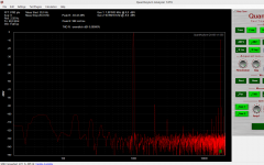
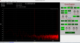
From left to right :
Kean buff without distortion trim, with analyzer cancelation, best copy of the input signal.
Kean buff without distortion trim, with analyzer cancelation, best copy of the input signal.
Good! It is odd that you need such a high resistor. Can you use a multimeter to measure the Vbe of a few transistors from the same batch you built it with?
Sure, it´s odd and i will measure Vbe.
Installed now 270 Ohm in both channels and they measure very much the same.
Will listen tomorrow.
Could not find a trim with lower value.
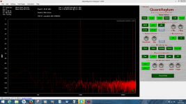
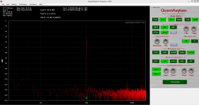
Measured the TKD pot at -30dB and -70dB.
No distortion so this red herring is from the table.
Installed now 270 Ohm in both channels and they measure very much the same.
Will listen tomorrow.
Could not find a trim with lower value.
Measured the TKD pot at -30dB and -70dB.
No distortion so this red herring is from the table.
Attachments

Vbe with or without the circuit under current ?
I did not trim the test point for halve voltage though.
I did not trim the test point for halve voltage though.
Measure transistors out of the circuit, with nothing else connected that could affect the measurement. That's why I said to measure other transistors from the same batch, not the ones in the circuit.
That's fairly normal, so it seems something else is the problem.
What are the differences between your build and the current schematic? I'm guessing TP is very high right now. The problem with a 250R resistor is that your input transistor is running very low current.
What are the differences between your build and the current schematic? I'm guessing TP is very high right now. The problem with a 250R resistor is that your input transistor is running very low current.
If TP is at 4.5V right now, then R5 must have been too low to begin with.
Try making R1 39R, then adjust R5 to make TP 4.5V. Then trim R1 for distortion.
Try making R1 39R, then adjust R5 to make TP 4.5V. Then trim R1 for distortion.
OOPS. Your BC5x0C seem to be much like mine. Leave R1 and R2 at 56R and just adjust R5 so TP=4.5V. Then trim R2 for distortion.
If this doesn't work, then I'm not sure what's going on.
If this doesn't work, then I'm not sure what's going on.
R5 in my build is 4.7kOhm.
I wanted to trim that value but i never did, sorry.
Nevertheless the buffer measures great now.
I will listen and make the changes later.
Then i know the difference.
I wanted to trim that value but i never did, sorry.
Nevertheless the buffer measures great now.
I will listen and make the changes later.
Then i know the difference.
I have put the trimed buffer ( with 270 Ohm ) in my system and it works.
I do not know why i got that odd value of the distortion trim resistor.
I am also very busy with other things but i plan to look into this further when time permits.
I do not know why i got that odd value of the distortion trim resistor.
I am also very busy with other things but i plan to look into this further when time permits.
Kean,
Can you tell me what is the purpose of output resistor R10 (47 ohms)? Can it be of different value? I broke my 47ohm leads and hence am looking at my parts bin for alternative.
Thanks
Can you tell me what is the purpose of output resistor R10 (47 ohms)? Can it be of different value? I broke my 47ohm leads and hence am looking at my parts bin for alternative.
Thanks
From Kean's article :
Reduce output impedance
Output resistance at the emitter of Q4 may be negative or positive, and it's important to keep it from going negative or else you risk oscillation. For this reason I would recommend at least a 4.7R output resistor. The 47R output resistor was chosen for best compatibility with signal cables. Transmission lines are reactive by nature and without the right termination impedance, become a cascade of series and parallel resonators. Without termination, the cables become antennas for RFI. 22R-47R is a good range for damping cable resonances. Without termination, any buffer will resonate with the cable's series resonance mode; the 47R resistor was chosen to prevent this.
Kean,
Can you tell me what is the purpose of output resistor R10 (47 ohms)? Can it be of different value? I broke my 47ohm leads and hence am looking at my parts bin for alternative.
Thanks
- Home
- Source & Line
- Analog Line Level
- The Kuartlotron - keantoken's simple error-correction superbuffer